re the ground post chassis wire: I would tend to agree but the wire is there, no? So it might have been deemed helpful at some point. It may still be.
Often the advice about grounding is to try different schemes and use the one that works best. Some trial and error might be indicated.
On the absolute phase... don't change the Pearl or its connections to the preamp/amp. I would get the Pearl working quietly first. Then try flipping leads at the speaker -- to see how much better it is -- and then test flipping pins at the cartridge to see if it works OK.
Does that sound reasonable?
WOW !! $60 for an RCA socket.
Sadly, that’s the midway point. Some of the WTB go for $100+ a piece (as opposed to $60 for a pair). Either way, I’m pretty sure they sound like my Neutriks

Actually, 6L6 turned me on to these Rean connectors, which look phenomenal for the price ($2ea) NYS367-0 REAN / Neutrik | Mouser
I don't have enough knowledge to determine whether that is an issue or not. If it is, then what about swapping at the output?
That would likely mean that I couldn't use a shielded coax wire, and would have to settle on a twisted pair instead.
On the absolute phase... don't change the Pearl or its connections to the preamp/amp. I would get the Pearl working quietly first. Then try flipping leads at the speaker -- to see how much better it is -- and then test flipping pins at the cartridge to see if it works OK.
I would still appreciate if someone can comment on the why it is a bad idea to swap the out/ground leads of the Pearl.
Does it have anything to do with the fact that the shield/signal wire of the interconnect to preamp will be swapped?
I think the issue is that in a system of connected units "ground" -- aka 0V -- has to be common from input to output.
Unless, perhaps, ground in the one unit -- the phono stage for instance -- was floated and isolated from the system's absolute ground. Grounding in the Pearl as described doesn't do that.
That's my impression. Actually, I'd appreciate the opinion of the more experienced chaps on this too.
Unless, perhaps, ground in the one unit -- the phono stage for instance -- was floated and isolated from the system's absolute ground. Grounding in the Pearl as described doesn't do that.
That's my impression. Actually, I'd appreciate the opinion of the more experienced chaps on this too.
I would still appreciate if someone can comment on the why it is a bad idea to swap the out/ground leads of the Pearl.
Does it have anything to do with the fact that the shield/signal wire of the interconnect to preamp will be swapped?
That has always been my impression, or at least it’s why I didn’t choose that route. I just flip speaker out at the back of the amp.
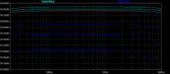
Substituting a 3.3V Zener diode for R10 (10k) will add about 1dB of gain to the first stage, and, as Vds of the input JFETs is reduced to about 2.8V there is less heating, better thermal compliance.
Illustrated:
Attachments
Illustrated:
I definitely want to try this one. Great observation!
I definitely want to try this one. Great observation!
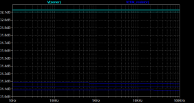
...except when you change one parameter, you have to change others. THD% is going to be higher according to my measurements.
gain is a bit over 1dB higher using the Zener.
it's very difficult to compare the sound -- I've soldered in some Molex female headers so R10 can be swapped out for the zener.
noise is equal under both circumstances.
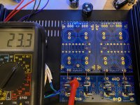
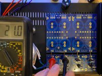
From the wise advise of 6L6 I decided to swap my little standard diode bridges for some MUR820's I had laying around in the parts bin. Now that they're in I think I have an issue. I'm seeing 23.3V at the secondaries but only 21V after the diodes. My mains voltage is about 123VAC. I measured all of the diodes in circuit and I'm getting the same parameters for all (8). I also tried swapping the secondaries and there was little to no change in the DC voltage. Do the diodes act differently without caps in the circuit or the PSU board not grounded at the moment? Or are all of my MUR's somehow bad? Should I stop typing and just solder the rest of the circuit together and test again?
Attachments
Yes the capacitors are an essential part of the AC-to-DC conversion circuit; leaving them out leads to unrealistic wild misbehavior which you can observe with an oscilloscope if you want. But who cares really; it's not a real world situation and the measurements merely answer the unimportant question, "What happens if I connect the components of my power supply incorrectly?"
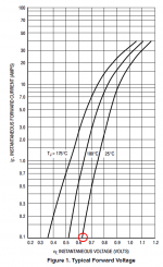
The datasheet of the MUR820 tells you what forward voltage (from anode to cathode) the diode will drop, when you're pumping 100 milliamps through the diode. Red circle. Now it is up to you to extrapolate and estimate what the forward voltage will be when you're pumping only 1 milliamp through the diode. {hint: think in decades. 1mA is two decades below 100mA}
_
Attachments
Looking at the photos it seems to me that the bridge board and the reservoir board are not wired according to the (idiosyncratic) configuration of the Pearl 2 PSU.
Shouldn't the bridges be connected together and the dual bridge connected to just half of the circuitry available on the caps board not all of it?
Shouldn't the bridges be connected together and the dual bridge connected to just half of the circuitry available on the caps board not all of it?
- Home
- Amplifiers
- Pass Labs
- Building a Pearl 2