Hej Knut,
Can you inform us about the current status of this project?
Regards,
John
Time is a precious resource, I am afraid. However, I have had time to initial listening tests, which resulted in a change in layout of the power supply, because of a quite load hum coming from the speakers.
After the modification, I still have some hum, but it is not that annoying during listening. And yes, the initial listening is promising.
However I hate to have sounds from my amplifiers that should not be there, so I am also planning to modify the amplifier PCB.
I also have to inquire whether my unregulated CRC power supply is sufficient for this amplifier.
I have used the weekend to further RC-filter the negative supply. This has reduced the hum to nearly inaudible level. I have used a 1 ohm resistor and a 22mF capacitor. I assume a doubling of the capacitor will remove the hum completely.
I have considered the use of a capacitance multiplier instead of the RC-filter, but the result has convinced me to go on with the RC-filter, and the additional voltage drop is less than 2 volts (on the negative leg).
I also have had time to listening test, and I must say I am satisfied with the sound. And as for my other earlier class A amplifiers, there is more than enough power - loud and clean is it.

The voltage at the source of the JFET is about minus 1.8 V when the output is at 0 V. This is enough to have a suitable current in excess of 1 mA in the P channel JFET. it works just fine.
And I agree with you about the topology.
Hy,
Are there any updates for the initial schematic on post #3 ?
Or any newer (better) pcb files than the ones in post #6 ?
I am willing to give this a try.
Thank you!
Thanks, i'll design my own pcb starting from the pdf you provided.I have not made any changes to the schematic and layout. I don't think I have some more PCB's, either.
I like this version of .LH amp because of the missing output capacitor.
Regarding the psu I'm into SMPS, I already have lots of good ones... with further LC filtering I had good results by now (even in AB class where the current is not constant)
I have not made any changes to the schematic and layout...
Any ideea what might cause not less than 700mv DC offset? I just can't bring it down. The parts used are as per schematic.
How much is recommended to measure across 0.47Ohm resistors?
Also, how hot should it get? This is my firs class A and everything burns, even the KOA BPR resistors.
Otherwise it plays nice with solid bass. Tnx!
Last edited:
The gate-source voltage for a given drain current of J5 (J175 in Post#3) is important. So if the offset voltage is too high and the bias current too high, I would assume that your drain current in J5 is too high.
The bias current should not be more than about 1.6 A (about 0.8 V above the 0.47 ohm resistors).
Is this error in both channels?
The bias current should not be more than about 1.6 A (about 0.8 V above the 0.47 ohm resistors).
Is this error in both channels?
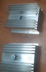
They're quite solid. The mosfets are connected directly to heatsink with high performance thermal paste. After less than 5 minutes the heatsinks are already burning and it seems like they keep heating. As I stressed before, even the 0.47ohm, 5W resistors are very hot - all this with less than 0.8V across them.
Attachments
I find it hard to measure and tacke photos at the same time.
I changed the mosfets to Infineon 47n60c3 (had them around) - I managed to obtain around 0.7V accros KOAs and now the offset jumped to 3V. Each pot has an a big impact on bias which makes it hard to dance between them in order to reduce offset and keep the bias.
The resistors still get damn hot (5W rated BPR58)... I powered the amp off when the resistors went beyond 65 degrees Celsius - meanwhile the mosfets were at about 55 degrees.
The circuit is powerd from +/- 24V and is set for SE.
The
Last edited:
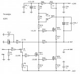
I have attached the schematic with some voltages.
If the bias current is far to high, replace R22 with a higher value (e.g. 470 ohm).
The idea is to set the bias with P23, then use P6 to adjust the offset. But as you mention, these potentiometer settings interact. So when the bias current increases when you are reducing the offset voltage, then you'll have to reduce the bias current with P23 again, and so on.
Please also observe that the ID-VGS relationship of J5 (J175) also is important. With a VGS-voltage of J5 of 2.7V, the drain current is 1.5 mA. But be aware: These values will vary with the JFET you are using.
Attachments
I find it hard to measure and take photos at the same time.
....
The resistors still get damn hot (5W rated BPR58)... I powered the amp off when the resistors went beyond 65 degrees Celsius - ...
Not sure why you want to measure and take pictures at the same time. Write down the number.
65 degrees C is NOT hot for a resistor. They are typically rated 200 deg C hotter.
Attachments
Last edited:
- Home
- Amplifiers
- Pass Labs
- NOStalgia - the all-FET JLH/PLH Class A amplifier