Hi everyone, i've just got some fancy 15R 200W variable resistors that i'm going to try using, i'm sure they will get almost as hot as a bulb too 
I hope my .8 K/W heat sinks will do it (with lower power anyway)
I was first thinking about a degeneration resistor but didn't want the local feedback so i thought about a bypass but realized it had to be pretty BIG so i'm
gonna go with (to start with) a battery for the negative bias supply.
Can i use a ~50k resistor between the gate and the negative side of the bias supply? (thinking gate leakage)
We all love pictures so i'll post some along the way too
finally buiding Fig 10 , i see no earth reference in the negative power supply schematic ? i have some LM337 negative supply board with ground reference can i use it with on the gate on the sit?An externally hosted image should be here but it was not working when we last tested it.
Last edited:
Hi, what is that schematic you posted from? Yeah, i think you could use that just fine (if it has the right voltage about minus 2-3v)
you connect the positive (ground in the schematic you posted) to the ground of the amplifier (same as the Source of the FET) and the negative (Vout from the LM337) to one side of the 47k resistor, and the other side of the 47k to the Gate.
TIP: Set your negative bias supply to ~12v and use a 5-10k multi-turn pot to adjust the bias with.
And please feel free to enlighten us if/what difference you hear with the fixed vs auto-bias
é

"French is not a crime"
Vive l´amitié franco-allemande......!
An externally hosted image should be here but it was not working when we last tested it.
Hi everyone, i've just got some fancy 15R 200W variable resistors that i'm going to try using, i'm sure they will get almost as hot as a bulb too
I hope my .8 K/W heat sinks will do it (with lower power anyway)
I was first thinking about a degeneration resistor but didn't want the local feedback so i thought about a bypass but realized it had to be pretty BIG so i'm
gonna go with (to start with) a battery for the negative bias supply.
Can i use a ~50k resistor between the gate and the negative side of the bias supply? (thinking gate leakage)
We all love pictures so i'll post some along the way too
Hello Chris,
I'll try to answer a couple of your questions:
1. .8C/W isn't going to be enough. Running these devices close to their limits without adequate heat sinking will probably lead to dissapointment.
2. A battery for the voltage reference presents the problem that as the battery drains the Id goes up and eventually your SIT goes poof, so you'll want to factor that.
3. You can try a 50K. If the Vdrop is manageable, then go for it. My SITs so far have show around 1uA of gate leakage current, which is minor, so I'm using 47K.
Hope that helps,
Mike
My thoughts are: get the 2SK82s from CircuitDIY Affortable Components for Hobbyists
As a general note, I'd like to point out that these devices are not MOSFETs.
To take advantage of the load line cancellation, you must consider both the operating point and the load when dialing in these SITs. With SITs, a small change in conditions can have a big effect on distortion and the mix of second to third harmonic, whereas MOSFETs are more forgiving because of their curves. I've worked up some examples of this for a future article.
Of course, once properly tuned, the SITs are magic.
I certainly encourage experimentation, but this is important to understand when you start plugging SITs into different circuits with different current sources, loads, etc.
My suggestion, when possible, is to build them as published then make your experimental comparisons from there.
Last edited:
yes I understand your intention Mike....
my deviations are more due to the lack of the bulbs but ....
I ordered already three 3,3 Ohm (50W) and three 1 Ohm resistors (50W) so I will build up a chain and "dial in" for the sweet point....
I also ordered the halogen sticks ZM recommended....
So in some days I will have the published version .......and will take it as basis.
Hello all !
I am reporting some values from my amps build :
I am pushing right now at 2 amps of current , which is obtainable - in my set up - with a 1500 halogen bulb ( 220 volt ) .
So at 16volt of Vds ( without degeneration example ) the halogen sticks offer about 13 ohm of load @ 42 volt of Vdd .
My couple of 2ks82 KD33 I have are a different match : -5,16 Vgs and -6,5 Vgs . I have ordered one more couple and hope to have a better match , even if I do not feel audible differences between the channels .
Now , at 2 amps the heat sinks run pretty hot ( with grease applied ) , so I will not take them that way for a long time , unless I find some bigger hardware in the next days .
Interesting is , that like in the DeLite amp - with my "6 ohm" speakers I "tend " to prefer a load around 15 or 16 ohm , which in that case of the Dmosfet the result of the bottom end of the music was a little more boomy but in a good way . Interesting -just , that the boomy effect is gone comletely listening to the Sits , so I think I will try the same configuration with a 16 ohm load ( around 1300 watt halogen bulbs ) and raise the current trough an higher VDD . We'll see .... and listen .
Soon back to 20 ohm and less dissipation .
By the way they sound very good @ 2 amps . Wonderful amp .
Sweeeet!
(what do you think Mike)
Resistors are fine (probably ever so slightly better). They're just not as glowy.

oh, I found some information about the meaning of KD-33 I think in an old manual of the Sony TA-N88
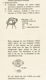
the marking seems to be the pinch off voltage (?) and the fluctuation of one Vp rank is acceptable, could been KD-33 and KE-33 is in a comparable range.
also interesting to know when I first measured the S-D resistance I was shocked by the low resistance and thought I had shot one, but look at the text, S-D is normally 1-3 Ohm and S_G and D-G should be diode characteristic........
I found some information about the meaning of KD-33 I think in an old manual of the Sony TA-N88 the marking seems to be the pinch off voltage (?) and the fluctuation of one Vp rank is acceptable, could been KD-33 and KE-33 is in a comparable range.
also interesting to know when I first measured the S-D resistance I was shocked by the low resistance and thought I had shot one, but look at the text, S-D is normally 1-3 Ohm and S_G and D-G should be diode characteristic........
Attachments
and for this .... for me and other people that do not know....
a similar problem was discussed here..
http://www.diyaudio.com/forums/solid-state/106964-sony-ta-n7b-vfet-help.html
The problem with these parts, apart form the price, was the very fact they were depletion mode, with Vp of about 25V for the J18/K60, and a whopping 55V on the J28/K82.
http://www.diyaudio.com/forums/solid-state/60972-hi-voltage-jfets-3.html
Attachments
Last edited:
with a 1500 halogen bulb ( 220 volt )
Don't you worry this is not a long time solution?
Because the halogen bulb will not reach the needed operating temperature (>240 degree celsius on the bulb) to recycle the vaporized tungsten back to the filament. Resulting possibly in a black bulb and shorter lifetime than expected.
Franz
Looking at Stefano's numbers and Gerd's Vp info. It looks like the grades may represent a fairly wide range of Vp, which relates to Vgs.
This isn't a big deal for Figure 10. And your devices needn't be Vgs matched precisely from channel to channel.
But, if you build Figure 11, and your KD-33's Id is more than 2.4-2.7A, you'll probably want to start building a separate bias supply and move on to Figure 10.
I got a couple of KE-33 and they biased-up at around -8V in Figure 10.
Last edited:
- Home
- Amplifiers
- Pass Labs
- L'Amp: A simple SIT Amp