Build the first one, exactly the way Nelson Pass designed it, using the parts Nelson Pass suggested.
Then if you feel the need to attempt an upgrade, build the second one according to your own inner voice. As they said at Burger King, Do It Your Way. Maybe you'll like it even more. Beware of "Proud Parent" bias, it's been recognized for 60+ years.
Beranek's Law:
Then if you feel the need to attempt an upgrade, build the second one according to your own inner voice. As they said at Burger King, Do It Your Way. Maybe you'll like it even more. Beware of "Proud Parent" bias, it's been recognized for 60+ years.
Beranek's Law:
It has been remarked that if one selects his own components, builds his own enclosure, and is convinced he has made a wise choice of design, then his own loudspeaker sounds better to him than does anyone else's loudspeaker.
This was nonsense.because I like a bit of headroom.

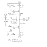
Honestly, I thought I was doing that. His Introduction to the BA-3 includes a discussion and specs for the 32V version. The caps I'm using are 1000uF, as specified, rated at 35V to be compatible with the power supply.Build the first one, exactly the way Nelson Pass designed it, using the parts Nelson Pass suggested.
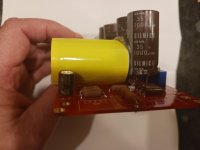
I think the comment is more along the lines that you have the PCB and therefore the ability to observe and measure the size of parts intended for the PCB, and yet bought enormous (although properly specced otherwise) capacitors that don't even remotely fit the board. Voltage rating and capacitance are not the only parameters you need to look at when ordering.
I think I used the same 1000uF 35V Slimic IIs in mine. I just leaned them over so they are mounted at a 20-30 degree angle (can't remember if that was inwards or outwards). I might look a bit weird, but with the box closed nobody will see it. And you'll know you have nice Silmic IIs in there 
I'm sure many of us have ordered parts that don't quite fit the PCBs on hand. (For example, I have a lot of trimmers with foot prints/adjustment knob locations that make their inappropariate) So just be mineful of dimensions/footprints and using the filtering tools (and reference datasheets as needed) will help avoid this in the future.
Slightly off topic: I'm trying to understand what's the expected voltages across C1 and C2 (at least under 'reasonable' operating condition (not grossly clipping) ). The BA3 article mentioned "The bias current here is about 50 mA, and it will deliver peaks of approximately 100 mA." Let's say Q3 gives 200mA, then the voltage acrosss R10 is 4.4V and the Vgs of Q3 (depending on what part you use) might be in the 3V (Toshiba) or 5-ish (Fairchild) range. Let's say 6V. So the voltage from the R6/R8 junction to V+ is should be less than say 12V.
Is this argument correct?
This sounds right to me - it is definitely much less than the supply voltage and lower voltage rated caps could be used, which is why my previous statement was nonsense.
Just measured my old boards with Fairchild Mosfets at 50 mA bias and the voltage drop across the caps is around 5V. In this case the 1V drop from R10 and 0.8V drop from R6 equalize so that the voltage is around the bias voltage of the mosfet. For AC signals the cap is more or less a short so that the voltage across the cap should really only depend on the biasing regardless of supply voltage even.
Just measured my old boards with Fairchild Mosfets at 50 mA bias and the voltage drop across the caps is around 5V. In this case the 1V drop from R10 and 0.8V drop from R6 equalize so that the voltage is around the bias voltage of the mosfet. For AC signals the cap is more or less a short so that the voltage across the cap should really only depend on the biasing regardless of supply voltage even.
Attachments
Thanks for the explanation. I had wondered about the actual voltage across the caps, but I'm not smart enough to figure it out on my own.
BTW, I was able to get the big caps to fit by bending a couple of 90s in the leads and mounting them about 1/4 inch above the PCB. I also glued them together for additional stability. They seem pretty solid. Hopefully, using the big caps won't adversely affect the sound quality.
BTW, I was able to get the big caps to fit by bending a couple of 90s in the leads and mounting them about 1/4 inch above the PCB. I also glued them together for additional stability. They seem pretty solid. Hopefully, using the big caps won't adversely affect the sound quality.
Attachments
- Home
- Amplifiers
- Pass Labs
- Burning Amp BA-3b (Balanced)