Thank you for the answer.
I put the NIC Components 12000uF 50V NRLRW123M50V30X50SF sound changed, became less distortion. I expect that there will be more bass, but for some reason it was less than Cornell Dubilier 6800uf.
Input kondentsatory I replaced the jumper without them a little cleaner.
I lack bass. Where to dig?
I put the NIC Components 12000uF 50V NRLRW123M50V30X50SF sound changed, became less distortion. I expect that there will be more bass, but for some reason it was less than Cornell Dubilier 6800uf.
Input kondentsatory I replaced the jumper without them a little cleaner.
I lack bass. Where to dig?
Dig for more bass with an amplifier with more than one output transistor in parallel. This little single transistor per rail 5200 is never going to deliver a lot of current, although it will try to destroy itself before blowing the rail fuses. In my case of now having almost 100,000uF per rail (and plans for more caps to make PS rail ripple lower), bass impact is better than stock, but it's clearly not a bass amp...
Ac coupling cap
Hello, does anybody know if the input coupling cap be bypassed, or is it necessary? I have a line on a pair for sale but the seller is asking a bit of a premium. If it turns out the caps can be bypassed that might be the nudge I need to take the plunge.
Thanks in advance.")
Hello, does anybody know if the input coupling cap be bypassed, or is it necessary? I have a line on a pair for sale but the seller is asking a bit of a premium. If it turns out the caps can be bypassed that might be the nudge I need to take the plunge.
Thanks in advance.

That's what I was hoping to hear. Thanks!funny - I can't find 5200 sch in my pc
however , if it's similar to 5400 regarding input stage - yes , you can short that input cap
that's idiot-proof part in there
Summer's here, and I'm pushing my luck with my over-achieving little 5200. I've got a fan blowing on it but prob need another one, as it gets very hot (can still touch for 10s) as the bias has been increased to 0.8A, so that's 20W of class A. PS ripple is below 6mV. More caps to add to get that below 5mV. And then I'll have to stop playing with it and move on to a proper F5.
....I'm pushing my luck with my over-achieving little 5200.
Yup, you are up to 31 - 32W per device now. As long as you can keep the heatsink temp reasonable it might hold up for a long time though. I would be more concerned about my speakers if the amp dies, this being due to the lack of DC output protection on this amp.
Fresh donor GFA-5200
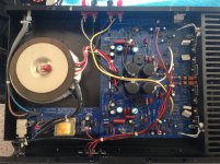
In my attempt to corner the market on used 5200's, I now have a newer updated GFA-5200 to play with (date sticker says 3-97). It has separate windings for the input stage, so input rails are +/-54V while output stage rails are ~42V. (Maybe it can swing the full output rails?) Then it also has separate PS (bridge rectifiers and caps) for each channel, so a useful advantage over the original.
It appears to have been assembled very quickly, and the input signal cable is actually RESTING on one of the rectifier bridges, so clearly cable routing is not one bit important to these hacks. Nor is capacitance: It has only 4 puny 6800uF caps, so it needs some help getting the PS ripple down from an unacceptable ~50mV.
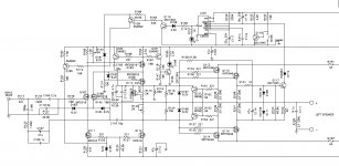
Now, "protection" is something they obsessed over: It has more transistors watching for faults (10) than for making sound (9). I will be referring to the schematic for the 5300 (attached) which is very close to the 5200.
It is my intention to replace the cover with a perforated aluminum cover which will be attached to the existing heatsink for maximum passive heat rejection without the use of a fan.
Stay tuned!
In my attempt to corner the market on used 5200's, I now have a newer updated GFA-5200 to play with (date sticker says 3-97). It has separate windings for the input stage, so input rails are +/-54V while output stage rails are ~42V. (Maybe it can swing the full output rails?) Then it also has separate PS (bridge rectifiers and caps) for each channel, so a useful advantage over the original.
It appears to have been assembled very quickly, and the input signal cable is actually RESTING on one of the rectifier bridges, so clearly cable routing is not one bit important to these hacks. Nor is capacitance: It has only 4 puny 6800uF caps, so it needs some help getting the PS ripple down from an unacceptable ~50mV.
Now, "protection" is something they obsessed over: It has more transistors watching for faults (10) than for making sound (9). I will be referring to the schematic for the 5300 (attached) which is very close to the 5200.
It is my intention to replace the cover with a perforated aluminum cover which will be attached to the existing heatsink for maximum passive heat rejection without the use of a fan.
Stay tuned!
Attachments
I'm so proud to hear that, fraggler!
But, by listening to me you've taken a big step toward blowing it up, so I agree it's a good idea for you to hear it for a while first.
What are you driving with it? Have you checked dc offset and bias yet? What is your ps ripple voltage? If it's much above 50mVAC then it may need recapping.
But, by listening to me you've taken a big step toward blowing it up, so I agree it's a good idea for you to hear it for a while first.
What are you driving with it? Have you checked dc offset and bias yet? What is your ps ripple voltage? If it's much above 50mVAC then it may need recapping.
This thread was in the back of my mind when I got a 5200 free with another purchase. This one is blowing those little fuses in the middle. In fact it had been replaced with 5 amp and I put 5's in and it also blew.
I am thinking its something in the PS side cos both fuses are going instantaneously when powered up. I think its the power supply caps.
could someone show me a circuit diagram. Mine has the 2 fuses in the middle of the board not 4. Is it same as an adcom 5002 ?
Thanks.
Srinath.
I am thinking its something in the PS side cos both fuses are going instantaneously when powered up. I think its the power supply caps.
could someone show me a circuit diagram. Mine has the 2 fuses in the middle of the board not 4. Is it same as an adcom 5002 ?
Thanks.
Srinath.
This thread was in the back of my mind when I got a 5200 free with another purchase. This one is blowing those little fuses in the middle. In fact it had been replaced with 5 amp and I put 5's in and it also blew.
I am thinking its something in the PS side cos both fuses are going instantaneously when powered up. I think its the power supply caps.
could someone show me a circuit diagram. Mine has the 2 fuses in the middle of the board not 4. Is it same as an adcom 5002 ?
Thanks.
Srinath.
The fuses that blow inside of the amp are the rail fuses, they are after the main filtering caps and will not blow when one of the main filtering caps fails. The fuse on the rear panel will blow when a main filtering cap goes bad.
The fact that oversized 5A rail fuses were installed means that whatever was failing is almost certainly dead now. I would expect to have to replace the output mosfets in the affected channel.
The adcom 5300 should be very similar only it has 4 outputs per channel versus the two in your 5200. The 5300 schematic can be found online.
Both channels
That's what got me thinking that its power supply - its both channels, and at the same time.
I have a few that are blowing 1 channel. That I know is transistors in that channel.
I guess the answer is still to test them and replace as needed.
Thanks.
Srinath.
The fuses that blow inside of the amp are the rail fuses, they are after the main filtering caps and will not blow when one of the main filtering caps fails. The fuse on the rear panel will blow when a main filtering cap goes bad.
The fact that oversized 5A rail fuses were installed means that whatever was failing is almost certainly dead now. I would expect to have to replace the output mosfets in the affected channel.
The adcom 5300 should be very similar only it has 4 outputs per channel versus the two in your 5200. The 5300 schematic can be found online.
That's what got me thinking that its power supply - its both channels, and at the same time.
I have a few that are blowing 1 channel. That I know is transistors in that channel.
I guess the answer is still to test them and replace as needed.
Thanks.
Srinath.
- Home
- Amplifiers
- Pass Labs
- Summer / Consolation Amplifier: 1995 Adcom GFA-5200