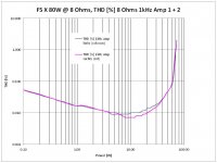
Could you perhaps show a THD plot below 0.05% ?
Patrick
As requested a plot with logarithmic THD scale for better resolution.
It's also a comparison between my 2 monos.
Attachments
Last edited:
After listening a few days now these babys seem to be played in. They became smoother every day and man do these go low. Incredible low end.
What are they driving ... BLS ? How will they handle the load of 2 1500's ?
Contingency ?
Cigar time !
What are they driving ... BLS ?
No, Radian/Truextent, BLS Horn, 1400ND, new custom speaker project. But that's another story.
How will they handle the load of 2 1500's ?
JBL 1500AL's ? 2 per side? I expect no problems.
Nelson said about the F5 "It will drive a 2 ohm load without burping, and 1 ohm without misbehaving."
The X version won't do worse
")
Attachments
Last edited:
Outstanding effort
It's great to see proof of the IRF outputs in a Balanced F5!
In addition, you did the project without a huge expense for a case or PCBs any regulated power supply.
I tip my hat to you...
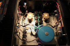
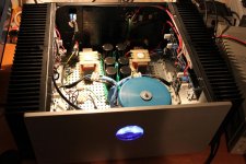
Here are some pics of the finished amp.
It's great to see proof of the IRF outputs in a Balanced F5!
In addition, you did the project without a huge expense for a case or PCBs any regulated power supply.
I tip my hat to you...
It's great to see proof of the IRF outputs in a Balanced F5!
In addition, you did the project without a huge expense for a case or PCBs any regulated power supply.
I tip my hat to you...
Thanks!
Did you also build an F5X? Or do you just plan it?
Thanks!
Did you also build an F5X? Or do you just plan it?
I did a Cascoded Balanced F5.
I started it about a year ago (around the time the group buy for the ongoing XF5 began) and finished it about 8 months ago. It was very easy and straightforward to build once I got over the prejudices of some of the forum members.
I used the Conrad heat sinks, degenerated complementary pairs, and the Toshiba outputs (I tried the 2SK1530/2SJ201 as well as the 2SK3497/2SJ618).
My total cost was under $600 from scratch. I was interested in trying the IRF outputs, but I was new to amp building and was talked out of it.
I have a J2 clone I'm experimenting with, and a secret weapon I'll bring out once I decide how to use the devices (the hint is the devices rhyme with "fit"). I'm on the sideline for a while, I move in a few weeks and I'm busy packing.
Design
Amp Boards X-ed as described at the beginning of this thread
Post #1
Amp Data
- Transformer 800VA, 2x18V per mono block
- PS CLC 2x 33.000uF 33.000uF 2.2mH/0.12Ohm 33.000uF; total 198.000uF per mono block
- Vrail +/- 21.8V
- Ibias 1.3A per output FET (gives 0.29V across R11/12), 2 output pairs! X-ed 4 output pairs
- output FETs IRFP240/IRFP9240
- input Fets 2SJ74BL/2SK170BL
- app. 70W into 8 Ohms, voltage clipping
- app. 130W into 4 Ohms, voltage clipping
- app. 175W into 2 Ohms, voltage clipping
- app. 200W into 1 Ohms, current clipping
Changes made to schematic
R10 = 33,2k
R21/22 = 22k
R17/R18 = 702
R117/R118 open
R11/R12/R111/R112 = 0.22
That’s it.
Hellol JBL4435,
With such a big psu, why would your amp not double power from 4-2 ohm..?,
Hellol JBL4435,
With such a big psu, why would your amp not double power from 4-2 ohm..?,
You loose a lot of voltage at higher currents. Under 2 Ohms the current limiting kicks in.
Yes, I know there is a thread giong on F5X EUVL Approach but the diy Store boards are available and why not use them?
I'm currently building 2 mono F5X with the P-F5c-2V20efrom the diyAudio Store.
those are the boards with cacode option and 2nd output pair option.
I'll build the 2nd output option and "X" 2 boards for a mono block.
AFAIK Smyslow did this with the 1 output pair boards but it was not further commented.
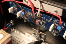
To "X" the boards two pcb connections need to be cutted. Not nice but the boards have no "X-Option". See picture.
Here are my first 2 questions to the knowledgeable:
1. Input impedance
If I go with the 1k input resistir plus 100k reference to ground as in the original F5 I'll end up with only 500 ohms input impedance in a X design. This is fairly low. I built my AX amps with 10k input impedance and 10k reference to ground.
Here I would like to go with 22.1k input impedance and 221.1k reference to ground.
Would this be ok?
2. Relative DC offset resistors output to ground
Would it be helpful to implement the output to ground resistors from other X designs (33 to 68 ohms plus/minus output to ground) also in this design? Or is it unneccessary? If yes, why?
hello. do you realy need to cut the connections? it look like you can just lift one side of the resistors R1, R2 and wire the X from there.
Last edited:
hello. do you realy need to cut the connections? it look like you can just lift one side of the resistors R1, R2 and wire the X from there.
Of course you can do that. You'll have 4 resistors hanging around then.
Of course you can do that. You'll have 4 resistors hanging around then.
not realy. they will be the tip of the wires you need to x the 2 PCB's.
then you don't need to damages the PCB's.
- Status
- This old topic is closed. If you want to reopen this topic, contact a moderator using the "Report Post" button.
- Home
- Amplifiers
- Pass Labs
- F5X from diyAudio Boards P-F5c-2V20e