Thanks Guys, It looks like I'll be doing a couple sets of matching in the future. I mentioned this earlier, but are the output boards a place that can benefit from quality cement resistors. I haven't seen them recommended by NP but do see them in some high end builds.
Also, can someone explain the interaction/relationship between the adjustments on the front end and the bias boards? Is one more critical than the other - and in combination - is DC offset still the factor to key on?
Also, can someone explain the interaction/relationship between the adjustments on the front end and the bias boards? Is one more critical than the other - and in combination - is DC offset still the factor to key on?
Last edited:
Hi Bob,
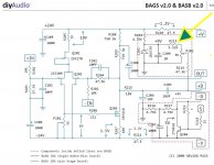
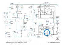
C3 between the front end and the output boards isolates any adjustment interaction.
Assuming that everything is wired and working correctly; start with the output board, adjust P202 for minimum offset; then adjust the front end; bias and adjust for minimum DC offset, measure at the junction of R215 and C203; there will be some variation on the output as you are adjusting the front end - ignore it; when you are finished, recheck the output board DC offset, it should be the same value as you set it earlier.
Fantastic !! Thanks. I'm collecting lots of pieces to the BA-3 puzzle. Maybe we will be able to consolidate them into an "Initial Start-up/Adjustment Guide" similar to those available for the F5. Most of what I'm learning is logical and straight forward, but I suspect others besides myself have shied away from these amps due to an "apparent" complexity. This is a different world beyond the "Build Your eBay Kit" where many of us started. If I make it through without any of that stinky green smoke or sparks, I'll start a project to create such a guide an invite all you "gurus" to dial it in.
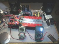
Well, this is what I came with in spite of Mother Nature. Around 2 PM Friday we had a "Michigan Hurricane". It took out the electricity and internet till about an hour ago. Remembered my butane soldering iron and LED lamps and carried on. ")
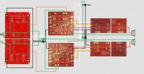
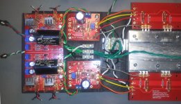
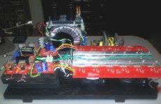
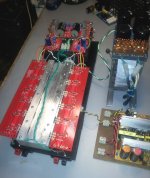
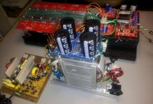
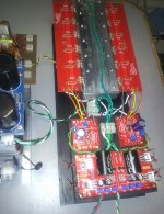
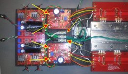
Haven't powered up yet cause I wanted to have other eyes check the wiring diagram. There are probably several ways to skin this cat, but I think it is correct. Please let me know of any problems and/or shortcuts.
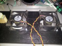
Not knowing about the heat yet, I pulled out two IBM server fans that are suitable for the Boeing wind tunnel. They are too loud for regular use but should work till I get a feel for just how much heat is produced.
I'll hold off till the morning - so like they say in NYC - if you see something, say something.
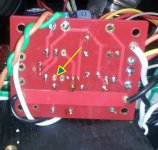
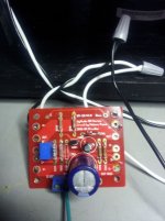
Note: The red/black wires at the sides of the front end are just temporary for the adjustlents. Modified PC PS to power fans will also disappear.
Haven't powered up yet cause I wanted to have other eyes check the wiring diagram. There are probably several ways to skin this cat, but I think it is correct. Please let me know of any problems and/or shortcuts.
Not knowing about the heat yet, I pulled out two IBM server fans that are suitable for the Boeing wind tunnel. They are too loud for regular use but should work till I get a feel for just how much heat is produced.
I'll hold off till the morning - so like they say in NYC - if you see something, say something.
Note: The red/black wires at the sides of the front end are just temporary for the adjustlents. Modified PC PS to power fans will also disappear.
Attachments
-
 Full Wires BIG.jpg172.1 KB · Views: 392
 -
 20130720_225337.jpg138.5 KB · Views: 396
 -
 20130720_225308.jpg121 KB · Views: 376
 -
 20130720_225438.jpg274.9 KB · Views: 382
 -
 20130720_225514.jpg103.4 KB · Views: 363
 -
 20130720_225606.jpg193.4 KB · Views: 174
 -
 20130720_225624.jpg134.3 KB · Views: 168
 -
 20130720_225644.jpg594 KB · Views: 170
 -
 20130719_151834.jpg91.2 KB · Views: 176
 -
 20130720_231733.jpg72.3 KB · Views: 163
Last edited:
Powered up semi-successfully. First thing I saw this morning were the missing power leads from the bias boards to the FE. Installed those and applied AC. No sparks but there seems to be some power drop that I believe should not be there. The PS (500 VA/18) unconnected reads +/- 25.4 VDC. When attached I get 18.3 at both 3 point terminal strips. That's with no adjustments - just a 10-20 second initial application of power. Any advice?
I can see some paths to simplify the power chain and that may be the problem. It was one of those build it first - then draw the diagram things.
I can see some paths to simplify the power chain and that may be the problem. It was one of those build it first - then draw the diagram things.
Attachments
Last edited:
Class A sag. Another guy is having same issue with his F4 build. You will have some drop across the rectifier bridge, small amount across the CRC, then rest is just transformer bending under pressure. Idea of what to expect from secondary for cLass A is, V-sec x 1.3. Your rail should be within a volt or two of this number. 18V secdondary should give you about 23V. It is related to total bias, of course.
OH MAN ! Had it and lost it 
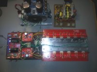
The amp fired up great with both channels full on, I think. I say that because the stage was very dispersed - more than any other build I've completed. After about thirty minutes of play, one channel (closest in photo) started to fade and went to a low level jumbled output.
I had 1 volt on all the front end check points, and ~ 0.03 mV DC on both sides when things were in order. Now the faulty channel reads just over 13 volts DC offset, the FE points are ~ 0.98 volts and the trimmer has no effect. The other channel appears to be stable. I'll double check the wiring, but it sounded like something just died over about a two second span. The room temp is 28 C and nothing went past 36 C - thanks to my Boeing wind tunnel fans.
I don't know if it is helpful for diagnosis, but compared to the F5 fed by the same Walkman - through the same bench speakers, there wasn't as much bass and not as much power as I had expected from all those output transistors. That may be due to the sagging trani and/or not enough capacitance in the PS. The sound was clean with no hum or distortion, but as I said, seemed very dispersed and almost a tad out of phase. Hard to tell with one speaker reflecting off the computer monitor. I didn't get a chance to hook up some bigger speakers in a different room.
Any suggestions on where to look first ?
So close, and yet......
Attachments
Last edited:
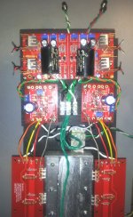
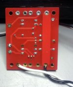
Wish this was my first build so I could claim nubee status, but I found an unsoldered lead on the bias board at R213. Probably took out Q204. I'll get a new one and try again. Do you think the caps should also be replaced?
Attachments
 Just starting readings now.
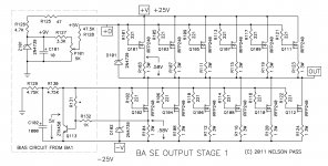
I wouldn't assume Q204 is bad. Before a re-attempt, I would make sure the front end and bias circuit were functioning normally without the output stage. If the front end voltages are normal, and DC offset is zero and stable at R215, and that top bias circuit is set to output ~4.5 volts or so at R214... then I would start thinking about re-connecting the output stage. And with a bunch of unmatched output devices you could have some doing all the work and some that are just "loafing".


I did. Removed the bias board and attached the PS directly. I wrongly read the schematic as 5 volts coming from the negative rail to Q204, but either hit the wrong pin or shorted two and sent the full load to the transistor. I have a tester function on my meter that I have never used, so I'll dig out the user docs and check it out. Not too hopeful though.
Attachments
- Home
- Amplifiers
- Pass Labs
- Burning Amp BA-3