I really like to try this BA-3 amp in my system but after looking for 2SJ74 in my local market ( Indonesia) I give up.
my question is can I use IRF9610 and IRF610 with this configuration ?
and before I burn my finger because to much current in my 9610 can somebody help me what I should do.
Thank You
my question is can I use IRF9610 and IRF610 with this configuration ?
and before I burn my finger because to much current in my 9610 can somebody help me what I should do.
Thank You
So JFET quiescent drain Voltages and channel currents are forced same.@kenpeter: why an IRF610 in the tail?
One drain already driving an IRF610 in the output stage, now both do...
Pretty much eliminates the need to trim for equal current in both legs.
The middle leg dumps any mismatch, as it shunt regulates tail current,
and doubles the open loop gain.
Last edited:
I really like to try this BA-3 amp in my system but after looking for 2SJ74 in my local market ( Indonesia) I give up.
my question is can I use IRF9610 and IRF610 with this configuration ?
and before I burn my finger because to much current in my 9610 can somebody help me what I should do.
Thank You
Try this, still working.....
")
Store
I was missing the connection to the drain last time.
With respect to THD, D. Self nicely showed that one needs well balanced DC-currents in the differential pair, so I assume you refer to DC-balance.
If so, your shunt reg should work only at DC, which it clearly does not. It also acts at AC, which is an entirely different story as the tail current becomes modulated.
AC tail current modulation does not appear to me to bring straightforwardly only positive improvements, so I would be curious about your arguments.
Also, I don't see why this shunt shall double OLG of the input stage as it is not an active load with almost infinite impedance like a current mirror.
Hannes
So JFET quiescent drain Voltages and channel currents are forced same.
One drain already driving an IRF610 in the output stage, now both do...
Pretty much eliminates the need to trim for equal current in both legs.
The middle leg dumps any mismatch, as it shunt regulates tail current,
and doubles the open loop gain.
With respect to THD, D. Self nicely showed that one needs well balanced DC-currents in the differential pair, so I assume you refer to DC-balance.
If so, your shunt reg should work only at DC, which it clearly does not. It also acts at AC, which is an entirely different story as the tail current becomes modulated.
AC tail current modulation does not appear to me to bring straightforwardly only positive improvements, so I would be curious about your arguments.
Also, I don't see why this shunt shall double OLG of the input stage as it is not an active load with almost infinite impedance like a current mirror.
Hannes
Thank You for your suggestion, can not buy from overseas its cost to much.
Can't get 1V across R10 or R11.
P1 and P2 are 500ohm. Max resistance creates 0.5V on R10 and 0.1V on R11.
Have tried adding 470ohm to P1 and P2 and this makes no difference although I'm not sure I've broken the trace fully.
Just checking that Q3=2SJ313 and Q4=2SK2013.
Any thoughts?
Chris
P1 and P2 are 500ohm. Max resistance creates 0.5V on R10 and 0.1V on R11.
Have tried adding 470ohm to P1 and P2 and this makes no difference although I'm not sure I've broken the trace fully.
Just checking that Q3=2SJ313 and Q4=2SK2013.
Any thoughts?
Chris
Thank You for your suggestion, can not buy from overseas its cost to much.
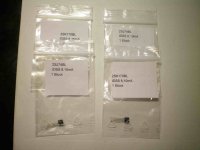
I can send you these two pairs matched by a friend with a curve tracer......
PM me please
Attachments
I was missing the connection to the drain last time.
With respect to THD, D. Self nicely showed that one needs well balanced DC-currents in the differential pair, so I assume you refer to DC-balance.
If so, your shunt reg should work only at DC, which it clearly does not. It also acts at AC, which is an entirely different story as the tail current becomes modulated.
AC tail current modulation does not appear to me to bring straightforwardly only positive improvements, so I would be curious about your arguments.
Also, I don't see why this shunt shall double OLG of the input stage as it is not an active load with almost infinite impedance like a current mirror.
Hannes
I never said it was balanced, only that quiescent operating points
would match. Since the output is also SE, can't imagine why the SE
pair is a problem. Deliberately unbalanced the transconductance to
force a match at DC, contrary to common sense as that may seem...
Perhaps now falls in the category of a folded cascode?
Nor did I say that tail current was a constant, only that it would be
shunt regulated. It is an active shunt. The tail follows NFB with full
unity gain, rather than than the usual 1/2. Thus the open loop gain
is doubled.
Jung, Self, you keep referring to constant current balanced pairs.
They knew their stuff, but thats all like: Sso five minutes ago...
Q3, Q4 seems correct to me, is he polarity of the caps correct?
I'll go down to the garage and check.
Thank You for your suggestion, can not buy from overseas its cost to much.
cost to much? $4 for shipping.
Caps are in correctly.
Q3 and Q4 are Gate Drain Source from left to right (looking at front of case) I believe so these are round the right way (this time!).
correct!
The other BA-3 board has produced the same results. I'm running them at -25V-0-25V+.
Makes me think the mosfets are faulty in some way but if so very consistently.
Can't move forward on this at present.
Would using 1k for P1 and P2 make a difference? This difference in the voltage across R10 and R11; if P1 and P2 were not high enough would there be this voltage difference?
Makes me think the mosfets are faulty in some way but if so very consistently.
Can't move forward on this at present.
Would using 1k for P1 and P2 make a difference? This difference in the voltage across R10 and R11; if P1 and P2 were not high enough would there be this voltage difference?
- Home
- Amplifiers
- Pass Labs
- Burning Amp BA-3