You can separate the front-end from the output.
But the only thing you get for that is using up the transformers you have. (Which is pretty nice.)
Sorry, I was not yet aware of what you want try to tell me before.

And now I understand, you mean since the output psu not touching the gain rails, I will get nothing benefits from using the good transformers. Correct?
Thanks again 6L6.
Last edited:
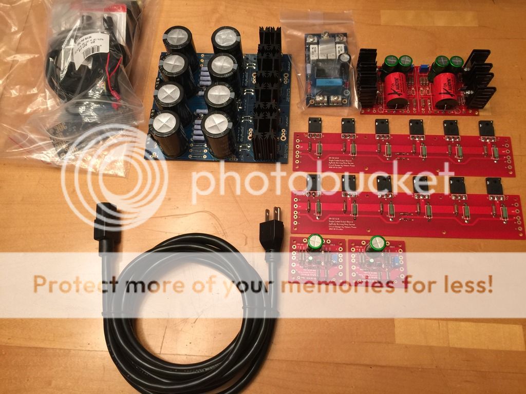
I've made great progress with my single-ended. The only thing I need now are the basic 5U chassis and an 18V transformer. Also waiting on matched jfets from user Alweit. I figured since most of my inputs will be of a fairly high level, I'm only going to use a preamp for phono. This means I'll still need a stepped attenuator, power switch, and input selector for the front panel.
Has anybody ever used these guys for rotary switches?
http://glass-ware.stores.yahoo.net/atandsise.html
Has anybody ever used these guys for rotary switches?
http://glass-ware.stores.yahoo.net/atandsise.html
I've made great progress with my single-ended. The only thing I need now are the basic 5U chassis and an 18V transformer. Also waiting on matched jfets from user Alweit. I figured since most of my inputs will be of a fairly high level, I'm only going to use a preamp for phono. This means I'll still need a stepped attenuator, power switch, and input selector for the front panel.
Has anybody ever used these guys for rotary switches?
Attenuators and Signal Selecters
I would have waited to solder outputs. Get them torqued down with keratherms, then slide board onto bent output pins, the solder. Since these are already soldered, and the solder joint is on top and easy to access, once bolted down, you might reflow then to prevent any strain on legs of outputs.
Russellc
wow stormfrontier that's really cool. 
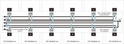
i also plan to build singe ended with 12 devices per channel.
but i think i want to make the output pcb's my self while learning at the same time.
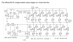
schematics based on official BA SE output stage.
please someone here help me to trace the pcb layout.
let me know if there are any mistakes, or any advice welcome.
thanks.
i also plan to build singe ended with 12 devices per channel.
but i think i want to make the output pcb's my self while learning at the same time.
schematics based on official BA SE output stage.
please someone here help me to trace the pcb layout.
let me know if there are any mistakes, or any advice welcome.
thanks.
Attachments
I would have waited to solder outputs. Get them torqued down with keratherms, then slide board onto bent output pins, the solder. Since these are already soldered, and the solder joint is on top and easy to access, once bolted down, you might reflow then to prevent any strain on legs of outputs.
Russellc
I'm not worried. I clamped them all flat on the table, put the spacers I'm using under the PCB, and soldered them all on. Since I'm doing the drilling tapping on a milling machine myself, I'm not too concerned about hole placement either.
Oh, and yes I used their on/off and selector switch in my BA-3 pre...I think I stole that idea from 6L6's BA-3 pre build thread.
Cool, thanks. They're cheap and seem like they're decently made.
Last edited:
hello again,
i have 4pcs Rcore single 32vac 180va each.
(that will be 2x32vac 360va for one channel)
if i separate the supply for gain stages.
is it okay to supply for the output stages?
thanks.
why not try the cascode from F5 Turbo V3 this cascode should also work for the BA3 frontend
So you could easyly use the transformers
Or i`m wrong?
Hi Danger Mouse,
Yes that is one solution using cascoded for a higher voltage rails.
But since the jfets k170 j74 very likes a low voltage, I think I have to make separate PSU for the gains rails.
And keep the voltage as low as possible without the help of cascode transistors.
Also, cascode and without cascode will "sound" quite different, and I like without.
18-20v is sweet enough for the jfets.
Last edited:
Hi Danger Mouse,
Yes that is one solution using cascoded for a higher voltage rails.
But since the jfets k170 j74 very likes a low voltage, I think I have to make separate PSU for the gains rails.
And keep the voltage as low as possible without the help of cascode transistors.
Also, cascode and without cascode will "sound" quite different, and I like without.
18-20v is sweet enough for the jfets.
I'm finding 31 volt rails pretty darn sweet.
Of course mine is complementary, not single ended.Taken from 6L6's build thread:
Complimentary output, 24V rails - 25WPC, 8ohm. More into 4ohm
Complimentary output, 32V rails - 40WPC, 8ohm. More into 4ohm.
Single-ended output, 24V rails - 25WPC, 8ohm. Less into 4ohm.
I guess you can go higher rails with single ended?
Russellc
Last edited:
Quick question: The single-ended bias boards only have P1, so I'm assuming that there is no "offset," and that the only thing that needs to be set for the outputs is the bias itself?
Also, the FE gets biased to 1V, or a little under. Do the output boards get biased to the same amount?
Also, the FE gets biased to 1V, or a little under. Do the output boards get biased to the same amount?
Quick question: The single-ended bias boards only have P1, so I'm assuming that there is no "offset," and that the only thing that needs to be set for the outputs is the bias itself?
Also, the FE gets biased to 1V, or a little under. Do the output boards get biased to the same amount?
Hi storm, I built the se version, the pot on the bias board zeroes the dc offset on the output terminals, the bias is fixed.
Hi storm, I built the se version, the pot on the bias board zeroes the dc offset on the output terminals, the bias is fixed.
Do you remember what the bias is fixed at for the outputs?
Do you remember what the bias is fixed at for the outputs?
I dont know if this helps, but with my complimentary BA-3, while the FE board biased like you say, from .900's to 1.000, the output stage, depending on room, circulation and so forth in a 5U chassis was limited to .46 or .50. Maybe this winter ( or with a babysitter ) a little higher. At this level the heatsink was reaching 52 degress centigrade.
Perhaps if someone with an up and running would measure across one of the resistors on the output board they could tell you, but if it is fixed, I guess it is fixed. I dont remember the BA-3 article mentioning it, but it may have escaped me as I was going complementary.
Anyone out there running a single ended BA-3 that wouldn't mind measuring this for stormfrontier?
Russellc
Last edited:
Do you remember what the bias is fixed at for the outputs?
I built it per spec with +- 25 volt rails, and 1 ohm source resistors. Bias is .58 amps per quasi comp pair. I have 6 pairs for 3.5 amps bias. I only use the se outputs and bias boards, I don't use the front end.
- Home
- Amplifiers
- Pass Labs
- Burning Amp BA-3