As for stabilization, this circuit is no worse than the usual diff amp and VAS setup in a conventional amplifier. It occurred to me this morning that I could sling another set of asymmetric gain mirrors between the diff stage and outputs This may allow me to remove some of the current input stage complexity - I'll see if I can gin up a simulation in the next week or so.
Re posts 334 and 34 from this thread, I'm finally getting off my behind and putting together a Class AB amp that utilizes the Mutant circuit as a front end to drive Exicon lateral mosfet followers for some serious AB action. Simulations are extremely promising. Let's hope the reality is as well...
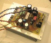
The beast is burning in on the bench as I write this. Current sharing between mosfets is decent, and I could make it even better by tweaking the source resistors up to 0R47 from 0R33. Output voltage with no signal is 2-3 mV, so I did an OK job matching the input mosfets.
Next I'll see how it behaves with an actual signal.
Next I'll see how it behaves with an actual signal.
This one coulda been a contender at BA '16, except that the XFMR I chose for it (a nifty enclosed/potted unit I picked up at Halted) hummed like an SOB when powered up with STD line voltage, and got worse over time (shorted turn?). The amp was loud enough to drown out the hum, but I didn't want to risk a transformer meltdown mid-play.
I just opened up and eviscerated an old amp I built in '78, extracting its power transformer, a hefty EI type with end bells and hum strap, originally intended for a Scott Alpha 6 power amp (just found that out last night). The transformer should fit nicely in the new amp and give it some heft and authority. I felt a little bad for cannibalizing an amp that gave me 20+ years of faithful service, but it had been sitting on the shelf for a number of years, and was not likely going to be fired up again. It was built using whatever bits and bobs I could scrounge in Ithaca, NY in the late '70s. The transformer came from BnF Enterprises, a surplus outfit long defunct...
I just opened up and eviscerated an old amp I built in '78, extracting its power transformer, a hefty EI type with end bells and hum strap, originally intended for a Scott Alpha 6 power amp (just found that out last night). The transformer should fit nicely in the new amp and give it some heft and authority. I felt a little bad for cannibalizing an amp that gave me 20+ years of faithful service, but it had been sitting on the shelf for a number of years, and was not likely going to be fired up again. It was built using whatever bits and bobs I could scrounge in Ithaca, NY in the late '70s. The transformer came from BnF Enterprises, a surplus outfit long defunct...
Last edited:
It's been a while - I was ultimately disappointed with the frequency response of the original incarnation of the "Mirror Magic class AB amp, so I ginned up a version that has emitter follower drivers between the differential/VAS section and the lateral outputs. The Exicon laterals take 220 ohm gate stoppers to keep them from squealing. I may also try using some tiny powdered iron toroids to make some "dirty" inductors as gate stoppers (low Q, very lossy at high frequency), but not right this instant.
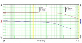
I've done some messing about, and as a result, have learned a bit more about compensation, resulting in the gain-phase plot you see here. A schematic may follow when things settle down a bit. My main thrust will be to make appropriate compensation mods to both amp channels, make some last G-P scans to satisfy myself, then button up the amp and do some living room testing to see if all the effort has been worth it.
My only wish at this point to to have a gain-phase analyzer that goes beyond 5 MHz to make certain that the gain passes down through 0dB and stays down there at higher frequency - gain margin as well as phase margin.
Attachments
")
I currently have one channel with a 1 uF cap mounted across R26, and one without. Small signal frequency response is pretty much identical for both. It may make a difference in large signal behavior, or if I decide to push the zero crossing out farther. I won't be doing that until I latch on to a gain-phase analyzer with a wider frequency range.
Right now the amplifier rise and fall times are ~2.8 usec, which is totally in line with the observed bandwidth as measured by the gain-phase analyzer. The rise and fall are also symmetric, which was one of the purposes of trying this amp, getting behavior similar to that of a complementary differential input stage with only one flavor of input devices.
The cap across R26 would be a lot more important if I were using a bipolar output stage
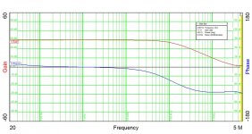
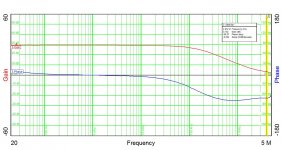

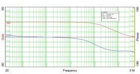
I amend my statement about peas in a pod - the first plot, which was done with the unit with 1uF across R26, shows what looks to be normal behavior at the 5MHz limit of the analyzer. The second plot, which is from a unit without the cap, shows an uptick in phase (blue trace) at 5MHz. I will obviously need an analyzer with higher frequency capability to investigate this, but my inclination would be to add the 1uF cap to the second amp channel as well. I plan to button these guys up in their case for now and find out how they sound, which of course is the purpose for this ridiculous exercise in the first place.
- Home
- Amplifiers
- Pass Labs
- "Le Mutant" Class A