So I have my F5 playing using a bench power supply that has 27V rails and can put out up to 10 Amps. I have read 2 different ways to bias the amp (Nelsons and someone else's post). I am using Cvillers V2 boards and TechDIY parts. I do have current limiting resistors and thermistors in the circuit. When I try to set the bias using what is outlined in the Pass manual I can get .59V over R11 and R12 but my DC offset is around 230mv. The other way described has you set bias so it is ok on one resistor and then use the pots to 0 out DC offset. When I do this the highest voltage I can get on R11 and R12 is around .3V. Each time I let the amp warm up and adjusted settings, inputs were shorted and the speaker terminals were left open.
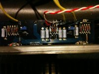
Am I doing something wrong? Could I have put a resistor in the wrong place? If so which location should I check first? It looks like everything is ok visually but some of the resistors are turned so I would have to remove them to make sure the values are proper. I would think that if I did make a mistake I must have made the same mistake on both boards.
Any help would be greatly appreciated.
Before I try different resistors I read somewhere that the pots on the board should be mirrored not oriented the same way. Do I have one of the pots going the wrong way on this board? I have measured R3 and R4 and one has the proper V and one is around 3V. This is true for both boards. Should I switch the one on the low V side around?
Attachments
having pots oriented is just matter of CW or CCW for increasing resistance
I'm not bothering usually with that - I always use ohmmeter to pre-set them ,prior to powering up ( if needed) .
in case of F5 -just be sure that you have them set to zero resistance , later voltage meters will tell you what's right direction to turning them
I'm not bothering usually with that - I always use ohmmeter to pre-set them ,prior to powering up ( if needed) .
in case of F5 -just be sure that you have them set to zero resistance , later voltage meters will tell you what's right direction to turning them
You are having a fairly common problem as of late. Mine did the same thing.
You need to increase the value (more ohms) of the resistor in parallel with the bias pots. R3 and R4.
Look at this post and read everything carefully -- http://www.diyaudio.com/forums/pass-labs/182723-how-build-f5-10.html#post2515520
FWIW, I was adding 2.2k resistors.
It will have the answers and a step-by-step procedure for you to follow. Although my amp uses the Peter Daniel boards, you will get the idea.
Good luck!
Thanks for the post 6L6 that is exactly what I was experiencing. I have been searching for days for someone having the same problem. What was your final resistance (~6.6k)? Do we know why this is happening lately?
If I just add extra resistors will it affect the sound? Should I order some higher ohm dale resistors and swap them out?
If I just add extra resistors will it affect the sound? Should I order some higher ohm dale resistors and swap them out?
The best guess as to why it needed the extra resistance is
1 . Idss of used Jfets is small ,or
2. Ugs of used mosfets is unusually big , or
3 . both 1 & 2
Regardless, it's not that big of a deal, as it's easy to adjust. Don't get any special resistors, just add whatever you have laying around in series to what's there.
The bias voltage reading is only valid if there is zero offset. Add some bias, adjust the offset to zero, add some more, re-adjust the offset back to zero, and so on until you have the proper .6v and zero offset. If you can't get the bias to .6 with zero offset, add more resistance.
Also, Only one of my channels has 6.6k, the other would bias nicely at 4.4k . Add only what you need.
Last edited:
So I went to radio shack and picked up some 1/2 watt 2.2k resistors and wired them up in series with R3 and R4. The good news is that I got one side to bias up to the right area. The bad news is that I shorted something on the other side and let the magic smoke out. Rather then just trying find the broken parts I am just going to order another kit from techDIY and a new board from the site. A little disappointing but at least I am on the right track.
On second thought I am going to just order another set of parts from techDIY and try to salvage the board. I am not sure how it will go but it will save me a little cash. Damn almost $50 worth of parts down the drain. Next time I will be more careful (I think I said that last time I broke something too).
On second thought I am going to just order another set of parts from techDIY and try to salvage the board. I am not sure how it will go but it will save me a little cash. Damn almost $50 worth of parts down the drain. Next time I will be more careful (I think I said that last time I broke something too).
Last edited:
OK so I pulled the bad board and removed the outputs. They were shorted. I didn't test the other fets but I am sure that they probably are bad too.
I received my new parts and board, poplulated it and installed it the other night. I put extra resistors on R3 and R4 off the bat. The board gets close but if I get to .59V I have about .05V offset. I know I could take the board out again and add extra resistors but I was wondering if that is close enough.
What is better 0 offset with a lower bias or 50mv of offset with the proper bias?
I plan on using the old board with the lifted trace and the new board to make an F5 car amp. Now if I could just find someone to make a SMPS that will work for me.
- Status
- This old topic is closed. If you want to reopen this topic, contact a moderator using the "Report Post" button.
- Home
- Amplifiers
- Pass Labs
- Weird F5 bias issue