Did you read the voltage across R7 while you had the power on?
With the power off, set your meter to Ohms and one probe on the Mosfet washer/screw, measure resistance with the other probe on each of the Mosfet pins and the Mosfet thermistor pins. All should read infinite resistance. This is to check to make sure the isolator between the Mosfets and the heat sink and the coating on the thermistors are not damaged and therefore conducting electricity to the mounting screw and heat sink and ground.
With the power off, set your meter to Ohms and one probe on the Mosfet washer/screw, measure resistance with the other probe on each of the Mosfet pins and the Mosfet thermistor pins. All should read infinite resistance. This is to check to make sure the isolator between the Mosfets and the heat sink and the coating on the thermistors are not damaged and therefore conducting electricity to the mounting screw and heat sink and ground.
Well, still have dim bulb failure.
You powered up with the amp channel attached and the light turned on and stayed on bright?

^^ do everything Ben said.
( Using the same color wire for both V+ and V- is a pretty dismal idea as he hinted at, I’d make a run to the hardware store and get something different for V-. )
Or at least get some green and red electrical tape and use it as a label for the wires. I'll admit I did that a while back because I didn't want to have to unsolder/re-wire.
")
--Tom
The dim bulb saves the day
I'd say I get the dim bulb award for the week.

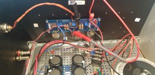
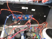
Your power supply voltage is good. Your wiring to the amplifier board looks good.
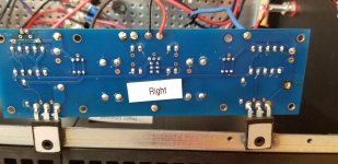
Looking at the P channel Mosfet (right side of board), the thermistor wire may possibly be contacting the washer/screw. Make sure that only the body of the thermistor is in contact.
Once that is done you are ready for power up with the dim bulb tester. Having two meters for the biasing is best, with one meter set to DC Volts on the speaker out and the other meter across R7, also set to DV Volts.
If all is good, the dim bulb tester should dim after intially glowing bright.
The voltage across R7 should be very low (much less than 1V).
If good, then biasing is next.
Well, I undid the errors with the Mosfets on Q3 and Q4. I double checked everything else on the boards.
But once again dim bulb rules and stays on. I did get a -434.2 reading off the speaker out. didn't get a reading on R7.
Appreciate any input.
Attachments
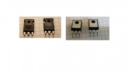
1. Your Mosfet or Mosfets may be damaged. Did you test them as Zen Mod mentioned in his post #1497?
2. Your -434.2 at speaker out- what are the units?
3. "Didn't get a reading on R7" -do you mean VDC = 0 across R7 or you did not measure?
4. Did you check Resistance between Mosfet pins and screw clamping Mosfet to heat sink? Check if you did not after remounting Mosfets. Should read high or infinite resistance.
5. Check VDC across R8.
Here are detailed instructions for testing Mosfets:
How to Check a MOSFET Using a Digital Multimeter | Homemade Circuit Projects
As I mentioned in post #1460, I'm not knowledgeable in trouble shooting the rest of the circuit. I've gone as far as I can.
Hopefully Zen Mod will step in and help. He can solve all problems.
Thanks for the How to Check a MOSFET reference.
Today's measurements:
Regarding #4 above: testing resistance on the MOSFETS I get:
For the right amp P Channel:
Gate OL
Source .047
Drain OL
For the right amp N Channel:
Gate OL
Source .048
Drain OL
For the left amp N Channel:
Gate OL
Source OL
Drain OL
For the left amp P Channel:
Gate OL
Source OL
Drain OL
On R7 I get OL.
On speaker out I get -427.6 mV
On R8 I get OL.
If one or more of the MOSFETS are bad I can replace all of them.
At least I'm learning a lot these days.
And thanks for your interest in helping me debug my handiwork.
- Home
- Amplifiers
- Pass Labs
- An illustrated guide to building an F5