Thanks to you 6l6 for the great build guide!
I need some help though with the biasing.
First time biasing one channel i read the voltage on the wrong resistor and accidently burned the r13/r14 resistors and output mosfets. I replaced all the burned parts but now i cannot bias that board. The mosfet does not generate any heat whatsoever even when turnings pots to above 0.6 volts on source resistors (r7/r8). Something that may be worth mentioning is that i cannot get less than 0.24 volts across the source resistors no matter how much i turn the pots.
Other board biases fine and i have run it for hours with low DC offset and approximately 0.59 volts at source resistors. And the mosfets generate heat.
I am guessing the trimpots may be at fault but they do change resistance across r5/r6 when turning with amp off and increase/decrease voltage on source resistors with amp on.
Thanks for any advice on what to do.
Thanks to you 6l6 for the great build guide!
I need some help though with the biasing.
First time biasing one channel i read the voltage on the wrong resistor and accidently burned the r13/r14 resistors and output mosfets. I replaced all the burned parts but now i cannot bias that board. The mosfet does not generate any heat whatsoever even when turnings pots to above 0.6 volts on source resistors (r7/r8). Something that may be worth mentioning is that i cannot get less than 0.24 volts across the source resistors no matter how much i turn the pots.
Other board biases fine and i have run it for hours with low DC offset and approximately 0.59 volts at source resistors. And the mosfets generate heat.
I am guessing the trimpots may be at fault but they do change resistance across r5/r6 when turning with amp off and increase/decrease voltage on source resistors with amp on.
Thanks for any advice on what to do.
Maybe fried JFETs?
What voltages do you currently see across R5, R6, R3 and R4?
Can you confirm your part values for R5, P1, R6 and P2?
Then with power off, when you adjust P1 through its range, what resistance
range do you see across R5? Same question for P2 and R6.
After mucking around with P1 and P2, don't power up again until you adjust them
so R5 and R6 have minimum value.
Last edited:
I have all the parts for a "DIY-Store Ver 3.0" power supply board. I am using 22000uF 35 volt capacitors. I am going to power an F5 Version 3 power amp from the DIY store. I want to use an "Antek" AS-3218 or an AS-4218. These two transformers have been out of stock for quite sometime. I called customer service and was informed that a shipment would arrive in 2 or 3 weeks.Is there another brand that is available? The "Plitron" web site is busted. Has anyone used a "Torid" https://toroid.com transformer with the same specifications as the two anteks mentioned. If someone has, could you suggest a model number.
I assembled an "ACA 1.6" I bought myself for Christmas. I had forgotten how good 2 channel music sounds. I had a "Big Ole Stereo" while I was in college. Somehow it got lost in the last 40 years. Thank God and Nelson Pass I kept all "487" of my Vinyl Albums. I don't know who invented "MP3" codec but I am going to punch them in the mouth when I get home.
Anyway back to the topic, I need more power. I think the F5 will fit the bill nicely.
I noticed the Plitron site being busted too. I have used their transformers in the past and was wanting to order my F5 toroid from them. I've used Toroid too in the past - for my build of Papa's Zen way back when.
Its ok to go larger on the transformer VA but don't over-do it because theres no real benefit, and there can be unwanted side-effects. Also try to find a shielded model to reduce stray field interference (i.e.: most offer an option to surround the toroid with mu metal shielding as well as having a static ground wire). The shielding options don't add much to the price. I recall Antek offers a shielded option too - so pay attention to the model #. I recall the "S" in the model number indicates shielding.
I checked the jfets and they indeed seemed fried, so I removed them and will and find some replacement. Seems like the lsk170/lsj74 are quite hard to find other than on the diystore, shipping to Sweden is a hassle so do you know if it is okay to use another pair different from the other board?Maybe fried JFETs?
Regarding what you said Dennis, the part values are the same on each board and from the f5-kit from the store (r5/r6 2.2k) (p1/p2 5k). The replacement resistors are the same values just other brands.
With power of and p1/p2 fully turned i could get r5/r6 resistance down to 0 ohms and turning other way increased resistance.
Unfortunately i cannot check the voltages now as i have removed the jfets but if replacing jfets does not fix the problem i will take those measurements and return to you.
Thank you guys for the great help, really means a lot for a beginner like me!
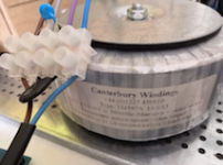
Can someone just sanity check my connections with CL60 / X1 cap placing please, I have been reading the threads for a while and just want to make sure this is OK for UK voltage? In case it's not visible on the image, the Toroid has 2 x 0-120V Primary (blue-grey + violet-brown).


it looks good (at least reading colors on xformer printing) , confirm proper polarity simply by powering it and checking voltages at secondary
though, be sure that shown arrangement with plastic connection block is temporary
NTCs gets hot in operation, and that's not bode well with these plasticky ones, nor tiny NTC legs goes well with screw connection
though, be sure that shown arrangement with plastic connection block is temporary
NTCs gets hot in operation, and that's not bode well with these plasticky ones, nor tiny NTC legs goes well with screw connection
it looks good (at least reading colors on xformer printing) , confirm proper polarity simply by powering it and checking voltages at secondary
though, be sure that shown arrangement with plastic connection block is temporary
NTCs gets hot in operation, and that's not bode well with these plasticky ones, nor tiny NTC legs goes well with screw connection
Thanks - yes, this is just mock up for power supply test (with bulb tester), I have proper connector block for later assembly.
Can someone just sanity check my connections with CL60 / X1 cap placing please, I have been reading the threads for a while and just want to make sure this is OK for UK voltage? In case it's not visible on the image, the Toroid has 2 x 0-120V Primary (blue-grey + violet-brown).
View attachment 849818
View attachment 849819
Take a look at this simple, easy to follow drawing @6L6 did at the front of this thread:
An illustrated guide to building an F5
Can someone just sanity check my connections with CL60 / X1 cap placing please, I have been reading the threads for a while and just want to make sure this is OK for UK voltage? In case it's not visible on the image, the Toroid has 2 x 0-120V Primary (blue-grey + violet-brown).
View attachment 849818
View attachment 849819
This looks correct for 240V. Put a dim bulb on it and power up.

- Home
- Amplifiers
- Pass Labs
- An illustrated guide to building an F5