") Found it - had a shortage on input cable...
Found it - had a shortage on input cable...Questionnaires to zen mod: i just built my first f5. The PSU is ok, used a 500va 2x18v transformer. Used the UPS boards. At the rails I have 25V. Everything OK. I found a short at the speaker posts, which I corrected. After mounting the MOS fets I found a short between the drain of the Mosfets and the heat Sink, although I used the keraterm foil. Then to my surprise, when I shorted the output and ground (of the PCs) my dmm made a noise: apparently there is a connection between the the two. Looking at the schematics that seems a bit odd to me. Anyway I am a novice at this and I would appreciate any advise from the experts.
Short circuit to ground
Hi,
I haven't been on this forum for some years now, but a recent problem with my F5 brought me back here. I've been happily using the amplifier 5 years until it recently stopped working directly after I turned it on. I checked the amp for burn marks or other visible damage to the components, but I couldn't find any. It turned out that the fuse was blown, so I swapped it for a new one and powered it back up while still having the lid off.
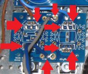
This time I heard a hiss and saw smoke coming from the thermistor TH1 between the PSU and ground. So there must be a short circuit to gnd, but I can't find it... or I don't know how to find it.
So I'm hoping that somebody could guide me in the right direction to find the error. Any ideas on to what could cause this sudden short circuit?
Thanks!
Hi,
I haven't been on this forum for some years now, but a recent problem with my F5 brought me back here. I've been happily using the amplifier 5 years until it recently stopped working directly after I turned it on. I checked the amp for burn marks or other visible damage to the components, but I couldn't find any. It turned out that the fuse was blown, so I swapped it for a new one and powered it back up while still having the lid off.
This time I heard a hiss and saw smoke coming from the thermistor TH1 between the PSU and ground. So there must be a short circuit to gnd, but I can't find it... or I don't know how to find it.
So I'm hoping that somebody could guide me in the right direction to find the error. Any ideas on to what could cause this sudden short circuit?
Thanks!
I did some more measurements with my DDM and I might be on to something.
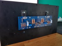
One of the rectifier board short circuits the pin 1 and 3 of all rectifiers on the board to the chassis. Meaning that it short circuits one of the outputs of the transformer to the chassis. The other board with rectifiers seems still fine. I wonder how this could happen?
The chassis acts as a heatsink for the rectifiers, so perhaps it insulation got damaged somehow???
Tomorrow I will remove the rectifier board from the chassis and measure it again, but first I need some sleep.
desolder bloody thingie (meaning - rectifier board(s) from rest of circuit and check them solo
then you'll know for sure where shortie to case is
if diode is dodo , just replace it , don't fret with cause
I see they're big , but indulge me - write exact type here , so we can think about possible current (doubt that, due to size) inability or - more likely - sissy voltage
if both are 'enough' ...... blame Gremlins
or me - Papa seems finding that lately as most convenient explanation , for 42 and more
I will desolder the rectifier board this weekend and check it.desolder bloody thingie (meaning - rectifier board(s) from rest of circuit and check them solo
then you'll know for sure where shortie to case is
if diode is dodo , just replace it , don't fret with cause
I see they're big , but indulge me - write exact type here , so we can think about possible current (doubt that, due to size) inability or - more likely - sissy voltage
if both are 'enough' ...... blame Gremlins
or me - Papa seems finding that lately as most convenient explanation , for 42 and more
The diodes are FEP30DP-E3/45
Thanks for the tip! I'll look into that if needed. What steps do I need to take to check for a faulty pwr supply cap?I recall a member having a smoking thermistor caused by a short in a power
supply cap. If no other issues present themselves perhaps this can be investigated?
I think that if your diodes have failed that may well be the short to ground.
If your psu caps have shorted, a continuity test with a multimeter may reveal that. Although, if its failed, with the amount of current going through it I would expect something visable on one of the capacitors.
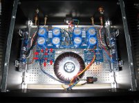
Youre safety earth wiring looks suspect.
Are you sure that the earth tag on the iec inlet is directly connected to where you attached the safety earth in the back chassis plate? As far as I'm aware the safety earth should go from the tag directly to the chassis. This point on the chassis would also form your star ground point. The ground going from psu board through the thermistor should then be fastened to that star ground bolt.
If your psu caps have shorted, a continuity test with a multimeter may reveal that. Although, if its failed, with the amount of current going through it I would expect something visable on one of the capacitors.
Youre safety earth wiring looks suspect.
Are you sure that the earth tag on the iec inlet is directly connected to where you attached the safety earth in the back chassis plate? As far as I'm aware the safety earth should go from the tag directly to the chassis. This point on the chassis would also form your star ground point. The ground going from psu board through the thermistor should then be fastened to that star ground bolt.
Thanks.I think that if your diodes have failed that may well be the short to ground.
If your psu caps have shorted, a continuity test with a multimeter may reveal that. Although, if its failed, with the amount of current going through it I would expect something visable on one of the capacitors.
Youre safety earth wiring looks suspect.
Are you sure that the earth tag on the iec inlet is directly connected to where you attached the safety earth in the back chassis plate? As far as I'm aware the safety earth should go from the tag directly to the chassis. This point on the chassis would also form your star ground point. The ground going from psu board through the thermistor should then be fastened to that star ground bolt.
The earth tag from the iec inlet is directly connected to the perforated bottom plate, but you can't see it in the picture. It's just behind one of the psu caps. The back plate is connected to the bottom plate with a wire, because it's coated and it would otherwise not connect to the rest of the chassis
- Home
- Amplifiers
- Pass Labs
- An illustrated guide to building an F5