6L6.... Jim.... Clear, concise, succinct of your F5 build. Great pics, too. Hopefully, no one will hijack your thread! (Can you get it "locked up"?)
Ooohhhh, Merlin--congrats on being the first and quickest to hijack this fine thread. Perhaps you ought to consider posting your own thread, on your build and problems. And yeah....the 2.2k ohm resistor is a BLEEDER resistor (there for your safety). In any case, where did you find a requirement for .47kohm (470 ohm) resistors in the power supply? They are not part of the design.... (If you want to answer, best to do in a new thread, or one of your existing ones).
And everyones, superb, congrats, Phenomenal, great spirit and positive enthusiasm, Clear, concise, succinct etc. etc. etc. is not hijacking? Not screwing up the topic? Not OT? And of coarse, As sic as it sounds "Perhaps you ought to consider posting your own thread, on your build and problems".

So we can be "HiJack free". Hey, we need another thread with 1 page of info for every 2 pages of what's in the last paragraph. Especially another F5 thread? If many members complained about all the chit chat in the original, and they can't read that thread
 what do you think they will say about the dozen odd, or more, F5 threads
 Sorry, call it like I see it

flg, CanAmMan, russellc -
Stop arguing about off-topic and threadjacking right now. Stop. Desist. Quit. It's not helping anyone. I have corresponded with all 3 of you at one time or another and am very surprised that you are acting like this.
Please guys, we are all friends here.
/rant
As I said before, because all the photos and captions are in the top posts, those pictures, descriptions, et. all., cannot get buried and stuck under a million random posts as my first thread did. All anybody needs to do, to see all the goodies in one place, it click the 'first' button. That's why I made this thread. To help people in making this phenomenal amp. If someone can glean some bit of insight in the assembly by seeing what I did (which in no way is the 'right' or 'only' way of doing it, merely a way) then my intentions have been fulfilled. I have been corresponding with a number of people in various stages of their build, from completely done to 'thinking about it' and everything in between. That has been a very rewarding experience for me, and I quite enjoy it. One of those people, whom got completely jumped on, is
merlin2069er - Yes, it seems that you installed the resistors in the wrong spot! The 2.2k are the bleeders, they should be installed across the input caps.(C1 and C3 on the pass schematic, not sure how the cviller board is labeled) The four .47ohm (not .47k) are between C4 and C7, C2 and C5. Your voltages do, however, seem a bit low.
russellc - My understanding is that the toshiba FETs need a slightly lower value, like you said, the common value is 1.5k . I too, invite people to share their observations and experiences with this. My case is most likely because the input FETs where all the way towards one side of their range, and the outputs on the other side of their range, and because of that combination of wonkyness, needed quite a bit more R to get the bias flowing. Anyway, it was a easy fix.
Ok, I've figured out what is happening. I must have been looking at the f5 service guide when I put together the PSU board. CViller's power supply boards labels are not in sync with that schematic.
So the correct value should be 2.2k ohm across the input of (T1 & T2) & (T3 + T4) and not .47kohms.
That's what has been popping my fuse. Silly me. I'll have to swap them around.
I've measured about ~15v dc & ~ 19v dc from the outputs of the bridges. Does that sound about right?
on cvillars board the 2.2k's are R1 &rR4 and yes the labeling does not agree with the pass diagram . your voltages besides from being very uneven are low if you're using an 18v tranny .
cheers Woody
By the way,
This time I really do not want to solder the board again (and risk lifting a trace)
no need to worry, it's close to impossible to lift a trace with modern fiberglass boards; not like in the old times with the paper boards where it was a piece of cake
Hannes
ok, I've wired up the ac inlet and switch to the psu (with the 2x cl-60's and capacitor)... (they were held in place by patch cables before).
Now I'm seeing about 19v+ @ V-in+, but my v-in- rail doesn't seem to give me anything.
I did swap the 2.2k and .47 ohm resistors around - I'm thinking I have a bad connection in the psu ( on that side) or possibly I smoked something.
I did see a puff of smoke before I blew my fuses...lol.
I've got to stock up on 2.5amp slow blow fuses - luckily I didn't use any 'audiophile' grade $40 fuse...
ok, I've wired up the ac inlet and switch to the psu (with the 2x cl-60's and capacitor)... (they were held in place by patch cables before).
Now I'm seeing about 19v+ @ V-in+, but my v-in- rail doesn't seem to give me anything.
I did swap the 2.2k and .47 ohm resistors around - I'm thinking I have a bad connection in the psu ( on that side) or possibly I smoked something.
I did see a puff of smoke before I blew my fuses...lol.
I've got to stock up on 2.5amp slow blow fuses - luckily I didn't use any 'audiophile' grade $40 fuse...
Build a light bulb tester it will save a fortune in blown fuses and smoking components. See page one of this thread.
Ok, I'll post some.
I connected one pair of primaries at a time to find out which pair of secondary windings to use.
I could double check, what method should I use to pair them up?
I don't know why they just don't use different color wiring to save a few headaches.
I connected one pair of primaries at a time to find out which pair of secondary windings to use.
I could double check, what method should I use to pair them up?
I don't know why they just don't use different color wiring to save a few headaches.
Last edited:
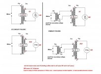
It most certainly does matter how you pair the windings, whoever you talked to didn't understand your question.
The transformer has 2 primaries and 2 secondaries. Each of those is a winding of a single wire around the core. Therefore you only have 4 wires around the core, with a total of 8 ends.
It's an Antek, so we know that the primaries are Red/Black, and the Secondaries are Blue/Green.
Also, we know that the primary leads are one black and one red. Also the secondary leads are one green and one blue.
Get your multimeter, and set it to continuity. (the setting where it beeps if you touch the probes.) put the probe on one of the black primary leads. Now touch the reds, one at a time. One will beep, that red is the mate to the black you are testing. Twist them together. Now double check that the other red and the other black also beep, and twist them. Those are now your 'A' and 'B' primaries.
Same thing with the secondaries - grab a blue, and test continuity to the greens, only one will beep. Those are mates, twist them together. Double check the other ones, and twist.
Last edited by a moderator:
flg, CanAmMan, russellc -
russellc - My understanding is that the toshiba FETs need a slightly lower value, like you said, the common value is 1.5k . I too, invite people to share their observations and experiences with this. My case is most likely because the input FETs where all the way towards one side of their range, and the outputs on the other side of their range, and because of that combination of wonkyness, needed quite a bit more R to get the bias flowing. Anyway, it was a easy fix.
I'm just joking about jacking, You did it the right way, post the whole thing at once, then let the info flow however. What output devices did you use in this build? IRF, Fairchild, or Toshiba? I assume not toshiba? I'll have some input soon, already have the standard value in place, I'm preparing to order 1.5K just in case. I'm using the Caddock resistors and doubling them would be difficult, so if it wont bias up, I'll just have to carefully change them...I do have a couple of spare boards just in case I trash one changing them out.
Thanks for the response,
Russellc
6L6, I just caught your statement about the input/output fets being "at one end of the range" and find this very interesting. What was the measurment of your input/output fets? I have more than one set, so I have some choices. I have suspected these little fets may make some difference in that resistors value needs to be. I would like to develope a feel for what "range" causes the variation, so any input much appreciated!
Russellc
Russellc
Last edited:
By the way,
no need to worry, it's close to impossible to lift a trace with modern fiberglass boards; not like in the old times with the paper boards where it was a piece of cake
Hannes
Not hardly. I have easily seen both the Cviller as well as Daniels boards with lifted and vaporized trace / pads, even with the greatest of care. Make no mistake, these two boards are very delicate in this regard. Best to avoid resoldering if at all possible. 6L6 did a nice job in his recent thread, and in a very effective way....unsoldering only one end, adding a series resistor to the empty hole, then soldering the two loose ends together. Half the soldering equals half the risk!
Russellc
It most certainly does matter how you pair the windings, whoever you talked to didn't understand your question.
Get your multimeter, and set it to continuity. (the setting where it beeps if you touch the probes.) put the probe on one of the black primary leads. Now touch the reds, one at a time. One will beep, that red in the mate to the black you are testing. Twist them together. Now double check that the other red and the other black also beep, and twist them. Those are now your 'A' and 'B' primaries.
Mybe I'm not understanding, but I was going to twist both red primaries together and both black primaries together, to the power input. I am obviously getting confused and perhaps this isnt the connection being dicussed. My first F-5 is dual mono with 2 tranformers and that is the way I did them, black to black, red to red. OK, tell me where I misunderstood so my headach will go away! (I am finding the single transformer version to be more confusing than the dual one I built) Thanks for the help and the nice pictorial, helping in another way as well, this time I am using a single Daniels power supply board like yours and your pics answer many questions.
I think you are talking about the connections to the CL-60s maybe? which I havent yet installed. I can see this is where a few builds may have gone bad....
Well looking at the first watt schemo I see what you are saying about the primaries now...not properly pairing them up could result in a lot of havoc, especially where they cross over to the CL-60s.
Russellc
Last edited:


- Home
- Amplifiers
- Pass Labs
- An illustrated guide to building an F5