apologies. not where the grease matters. Was intending the board itself. I see a speckling that I thought was grease on the board I assumed was from handling.Dear 6sx7,
No thermal grease under power tubes? Wouldnt that be a problem in conducting heat to heatsinks? What I used should be heat conductie but non-conductive for electricity I believe.
I love me some keratherm sheets I'm way to sloppy with the grease.
There is thermal grease I put between the thermistor and washer, to provide some heat transfer. I can clean it if it is not necessay. But grease is not conductive for electricity. I measured no continuity between the screw/washer and any of the legs of nearby parts such as thermistor, mosfet or other random parts such as resistors.Looks like it. He could measure a possible short, or just remove the washers and see what happens.
Looks like the goop covers both legs…
Since no one seems to nail this one first try, let’s try another approach: You say your PSU works fine. I assume this is without the variac.There is thermal grease I put between the thermistor and washer, to provide some heat transfer. I can clean it if it is not necessay. But grease is not conductive for electricity. I measured no continuity between the screw/washer and any of the legs of nearby parts such as thermistor, mosfet or other random parts such as resistors.
Are you absolutely certain the bulb arrangement is wired correctly?
Wrt the initial fuse-blow, this could have been due to your bias pots being set too high. Turn them all the way down. If you are certain the psu works, you could consider skipping the variac, and power one board at a time. Prior to turning on, put DMM’s across the source resistors. If voltage drop skyrockets on power on, turn off immediately. If not, and the boards light up (led), and the bulb is nice and as it should, slowly try to increase Iq/bias and see what happens across them source resistors.
I never tried bulb or variac. I find it adds complexity

Not using condoms while powering up is a good excuse to work meticulously. Of course, the occational fire has to be taken care of though

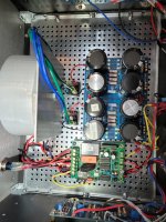
This is where it all began for me, building my first First Watt amp.
I recently ported over everything od that build to a 4U case. The 5U was too big.
But when I turn it on [amp boards not connected], the 3A slow fuse blows.
I thought it was the IEC, but It'sallinmyhead spent some quality time with me and now I've got a diyAudio IEC installed.
Before the fuse blows, the slow-start CB LED lights up, when I push the on button, that lights up and I hear a click from the slow-start CB, which tells me that is all working correctly.
I swapped out my original PSU board for a new one, but no dice, fuse still blows.
I'd appreciate some fresh looks at this.
And thanks
Attachments
Wrt the initial fuse-blow, this could have been due to your bias pots being set too high. Turn them all the way down. If you are certain the psu works, you could consider skipping the variac, and power one board at a time. Prior to turning on, put DMM’s across the source resistors. If voltage drop skyrockets on power on, turn off immediately. If not, and the boards light up (led), and the bulb is nice and as it should, slowly try to increase Iq/bias and see what happens across them source resistors.
I asked this earlier and bermek replied the pots were not adjusted prior to the power up.
The surefire way to set P1 and P2 is to turn them so that the measured resistances across R5 and R6 are low (ideally close to zero).
But what happens if you power up without first adjusting them? Let's for simplicity assume the pots came 'centred' so their values are about 2.5K (for the 5K pots) and the equivalent resistance across R5/R6 are about 1.2K. If your jfets are 8-ish mA Idss then after some degeneration they're drawing 6-ish mA. That gives you about 7.2V across R5 and R6, which is also the diff in voltage of the gates of Q3/Q4 to the respective rails. We know these mosfets are definitely 'on' with 4-ish volts Vgs. So let's assume a little over 5V there, and ~2V across the 0.47R source resisters. This implies about 4.2A current, which is very high. (Recall the standard current of the F5 is ~1.3A.)
Of course, if your jfet Idss is higher, the situation is even worse (though at some point, the 10A current limiter kicks in). On the other hand, if your jfets have lower idss then the situation may not be as bad. Either way, one really should set the P1 and P2 pots 'low' before the initial power up.
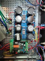
I have two PSU boards. One from the original F5 board, and one I built to swap in to see if the first PSU board was the issue.walk it back.
unhook everything.
hook up the slow start board and see if fuse pops. No fuse pop.
add x-former and see if fuse pops. No fuse pop.
add rectifiers and see if fuse pops. No fuse pop.
add PSU board and see if fuse pops. [New PSU] Fuse pops. I swapped in the original PSU board that that blew a fuse too.
Both PSU boards blow the fuse.
6sX7, thanks for the guidance
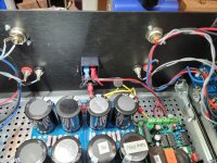
The bolt holding the transformer isn't touching the front of the case by any chance is it?
Amp boards not connected so it's either the xformer or the PSU or the slow start. I can't see if you have a shorted turn (xformer mounting bolt is making contact on the other side) but I would bet on a problem with the slow start. Try bypassing that first ... process of elimination.
Amp boards not connected so it's either the xformer or the PSU or the slow start. I can't see if you have a shorted turn (xformer mounting bolt is making contact on the other side) but I would bet on a problem with the slow start. Try bypassing that first ... process of elimination.
Great, I will look into this, it might very well be the culprit in my case. And how should P3 be adjusted? Thank you.I asked this earlier and bermek replied the pots were not adjusted prior to the power up.
The surefire way to set P1 and P2 is to turn them so that the measured resistances across R5 and R6 are low (ideally close to zero).
But what happens if you power up without first adjusting them? Let's for simplicity assume the pots came 'centred' so their values are about 2.5K (for the 5K pots) and the equivalent resistance across R5/R6 are about 1.2K. If your jfets are 8-ish mA Idss then after some degeneration they're drawing 6-ish mA. That gives you about 7.2V across R5 and R6, which is also the diff in voltage of the gates of Q3/Q4 to the respective rails. We know these mosfets are definitely 'on' with 4-ish volts Vgs. So let's assume a little over 5V there, and ~2V across the 0.47R source resisters. This implies about 4.2A current, which is very high. (Recall the standard current of the F5 is ~1.3A.)
Of course, if your jfet Idss is higher, the situation is even worse (though at some point, the 10A current limiter kicks in). On the other hand, if your jfets have lower idss then the situation may not be as bad. Either way, one really should set the P1 and P2 pots 'low' before the initial power up.
Center P3. You can come back to that later.Great, I will look into this, it might very well be the culprit in my case. And how should P3 be adjusted? Thank you.
For now, you can just leave that pot in the centre position, as P3 adjustment is best done in combination with distortion measurements. Please see this demo by 6L6:
Note there is no requirement to adjust P3 for the proper operation of the amplifier. It is used to tailor the distortion profile.
Some threads on this topic:
https://www.diyaudio.com/community/threads/adjusting-p3-a-video.259234/
https://www.diyaudio.com/community/threads/p3-adjustment-for-the-average-hobbyist.324902/
Ben Mah,Great, I will look into this, it might very well be the culprit in my case. And how should P3 be adjusted? Thank you.
You nailed it.
Duh!!!
Thanks so much for getting me out of Purgatory.
Chip

Thank you very much. This is informative.For now, you can just leave that pot in the centre position, as P3 adjustment is best done in combination with distortion measurements. Please see this demo by 6L6:
Note there is no requirement to adjust P3 for the proper operation of the amplifier. It is used to tailor the distortion profile.
Some threads on this topic:
https://www.diyaudio.com/community/threads/adjusting-p3-a-video.259234/
https://www.diyaudio.com/community/threads/p3-adjustment-for-the-average-hobbyist.324902/
👍🏽👍🏽😁
Saved by the fuse. The PS capacitors could have blown from the reversed voltage.
For first power-up, it's always a good idea to use a Dim Bulb Tester.
Sorry that you dear experts have to go thru us newbies’ ignorances.Ben Mah,
You nailed it.
Duh!!!
Thanks so much for getting me out of Purgatory.
Chip
That totally seems to solve my fuse-blow issue. I really appreciate it. I would never expect such a detrimental effect of that adjustment.bermek,
I would not recommend wiring up the amp boards to the power supply without proper heatsinks attached.
Does the dim bulb test with you remove both amp boards from the power supply?
Also, please measure the resistances across the R5 and R6 (2.21k) resistors. If you are not seeing low
values (say a few ohms or ideally close to zero) then you either have not adjusted P1/P2 or adjusted
them in the wrong direction.
Dear andynor, I made the correct adjustments on P1 P2. But amp is not working. The test speakers I use give extremely weak sound out, as if I would have directly connected the source to the speakers. And the heatsink is dead cold even after 10-15 min working. Where should I start my checks? Measure voltages at the legs of power mosfets? What should the values be? When I first powered on without pot adjustments the fuse had gone off. Do you think some of the fets fried?Center P3. You can come back to that later.
- Home
- Amplifiers
- Pass Labs
- An illustrated guide to building an F5