Dennis Hui, thank you for your feedback.I personally wouldn't worry about it. The main thing is to get the final bias current, with the amp warmed up, in about the 1.3A range (~0.6V across the 0.47R source resistors) and with the DC offset close to zero.
And don't forget to short the inputs for this procedure.
Also in the case of IRFP240 and IRFP9240, they are sufficiently different that matching between the the N and P channel parts isn't really feasible.
Yes, no load, and inputs shortened.
I went yesterday to ~0.6 V.
I stopped with a config:
0.65 V at N-mosfet across 0.47Ohm resistor,
0.55 V at P-mosfet across 0.47Ohm resistor,
0.025 V of a bias offset.
This means ~1.3 A +/- 8% margin, which is probably OK.
The heatsink temperature measured nearby the N-mosfet was 50 deg C and everything was quite stable during 3 hours.
I think then that everything is fine and will continue with the second channel.
N/P Iq diff is high, over 15%.Dennis Hui, thank you for your feedback.
Yes, no load, and inputs shortened.
I went yesterday to ~0.6 V.
I stopped with a config:
0.65 V at N-mosfet across 0.47Ohm resistor,
0.55 V at P-mosfet across 0.47Ohm resistor,
0.025 V of a bias offset.
This means ~1.3 A +/- 8% margin, which is probably OK.
The heatsink temperature measured nearby the N-mosfet was 50 deg C and everything was quite stable during 3 hours.
I think then that everything is fine and will continue with the second channel.
Where did you source your JFETs?
Edit: I saw your earlier post, please disregard the question.
I you want closer Iq between N/P, please post some pictures then we might be able to help you.
If you are in Europe, I can match up MOSFETs for you in a jiffy. But that won’t nescessarily cure your issue. But then, it might sound fine no matter what.
Regards,
Andy
Last edited:
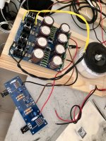
Dear experts. Kind of a novice here. I tried the amp as described in the guide and as you see in the photo (of course there are large heatsinks, currently not installed on). But when I powered up, it shortly blew the fuse. Parts dont seem to receive damage, at least on visual check. Carefully checked for misplaced parts, soldering errors, etc. and even did some continuity tests for some obvious short circuit possibilities. Replaced the fuse, removed one of the amp circuits from heatsink, plugged in on a dim bulb tester (Should have done it on the first place). Plugged in again, but bulb is shining bright. Where am I making a mistake on such a simple and straightforward circuitry? How should I go about diagnosing the problem? I’d appreciate if you help a newbie.
Attachments
Gremlins are everewhere, even in «simple» things. Start by disconnecting the amp board(s) from PSU and verify rail voltages (pos and neg) ref to «audio» gnd @ PSU center.Dear experts. Kind of a novice here. I tried the amp as described in the guide and as you see in the photo (of course there are large heatsinks, currently not installed on). But when I powered up, it shortly blew the fuse. Parts dont seem to receive damage, at least on visual check. Carefully checked for misplaced parts, soldering errors, etc. and even did some continuity tests for some obvious short circuit possibilities. Replaced the fuse, removed one of the amp circuits from heatsink, plugged in on a dim bulb tester (Should have done it on the first place). Plugged in again, but bulb is shining bright. Where am I making a mistake on such a simple and straightforward circuitry? How should I go about diagnosing the problem? I’d appreciate if you help a newbie.
Surely enough, that was one of the first things I did. 17V AC from the Transformer, comes out clean nice 22.2V DC between V+/Grd and -22.2 in V-/Grd.Gremlins are everewhere, even in «simple» things. Start by disconnecting the amp board(s) from PSU and verify rail voltages (pos and neg) ref to «audio» gnd @ PSU center.
bermek,
I would not recommend wiring up the amp boards to the power supply without proper heatsinks attached.
Does the dim bulb test with you remove both amp boards from the power supply?
Also, please measure the resistances across the R5 and R6 (2.21k) resistors. If you are not seeing low
values (say a few ohms or ideally close to zero) then you either have not adjusted P1/P2 or adjusted
them in the wrong direction.
Iaw picture? Positive is still connected there.Surely enough, that was one of the first things I did. 17V AC from the Transformer, comes out clean nice 22.2V DC between V+/Grd and -22.2 in V-/Grd.
In fact I had not made any adjustments on pots yet, once this is resolved I was going to ask about that. Would that adjustment be so critical as to create short circuit-like outcomes?bermek,
I would not recommend wiring up the amp boards to the power supply without proper heatsinks attached.
Does the dim bulb test with you remove both amp boards from the power supply?
Also, please measure the resistances across the R5 and R6 (2.21k) resistors. If you are not seeing low
values (say a few ohms or ideally close to zero) then you either have not adjusted P1/P2 or adjusted
them in the wrong direction.
I did not do dim bulb testing solely to the power board, since I measured correct rail voltages. Was this wrong idea?
Sorry, what did you mean by law picture?Iaw picture? Positive is still connected there.
Here is the one I tested alone.What's the other side of the board look like?
I did not do dim bulb testing solely to the power board, since I measured correct rail voltages. Was this wrong idea?
Best to test the supply alone first, but now you know it is ok.
Should snip off the extra length soldered leads on the bottom of board.
Is that thermal grease conductive? Best to clean it up either way.
and to second rayma, snip the ends of the leads or make sure they have enough standoff to not be shorting to anything.
Solder joints look nice and discrete, no overflow. Hard to tell on the jfet at the far end of the picture.
Next step would be to start checking for shorts on the board itself.
and to second rayma, snip the ends of the leads or make sure they have enough standoff to not be shorting to anything.
Solder joints look nice and discrete, no overflow. Hard to tell on the jfet at the far end of the picture.
Next step would be to start checking for shorts on the board itself.
Agree. Especially the two ends up at the left. They look as long as my standoffs at least. Also it looks like the output MOSFET on top right was under strain during soldering. Sometimes they can break, but still look fine. I’d check that too.
It is important that the fets have some leverage after tightening the board, ie possible to wiggle a bit. And solder them last.
Other than that, second the others advice.
Edit: Please also verify no continuity between fet center pins and sink. My eyes might be misleading me, but kinda looks like something protriding through the pad there.
For good measure I’d replace the pads and skip the goop, for testing at least. If Keratherm, drop goop.
Last edited:
gray spongy thingie ( any so called silicone pad) is recipe for disaster when knocking on 30W+ per mosfet area
in worst case ( still adequate) mica+goop
better - alumina oxide pads or Keratherm 86/82
proper torque most critical for Keratherm, for mica and al. oxide pads less critical (crank it by feel)
in worst case ( still adequate) mica+goop
better - alumina oxide pads or Keratherm 86/82
proper torque most critical for Keratherm, for mica and al. oxide pads less critical (crank it by feel)
Looks like it. He could measure a possible short, or just remove the washers and see what happens.Guys, take a look at Q3/TH1 on the board that’s installed on the heat sink. Is that thermal goop caked on it… that could be a problem. Using phone now so it’s hard for me to get a good look.
Looks like the goop covers both legs…
Last edited:
Dear 6sx7,Is that thermal grease conductive? Best to clean it up either way.
and to second rayma, snip the ends of the leads or make sure they have enough standoff to not be shorting to anything.
Solder joints look nice and discrete, no overflow. Hard to tell on the jfet at the far end of the picture.
Next step would be to start checking for shorts on the board itself.
No thermal grease under power tubes? Wouldnt that be a problem in conducting heat to heatsinks? What I used should be heat conductie but non-conductive for electricity I believe.
The output mosfets look fine, don’t have any broken legs. When you mention continuity between fet and sink you still talk about the power mosfets, right?Agree. Especially the two ends up at the left. They look as long as my standoffs at least. Also it looks like the output MOSFET on top right was under strain during soldering. Sometimes they can break, but still look fine. I’d check that too.
It is important that the fets have some leverage after tightening the board, ie possible to wiggle a bit. And solder them last.
Other than that, second the others advice.
Edit: Please also verify no continuity between fet center pins and sink. My eyes might be misleading me, but kinda looks like something protriding through the pad there.
For good measure I’d replace the pads and skip the goop, for testing at least. If Keratherm, drop goop.
I did not use insulation for screws when attaching the big mosfets to heatsink, assuming the black plastic surrounding the hole is isolation. Besides, did not read any continuity between heatsink and any of the legs of the mosfet.
So you recommend mica insulators?gray spongy thingie ( any so called silicone pad) is recipe for disaster when knocking on 30W+ per mosfet area
in worst case ( still adequate) mica+goop
better - alumina oxide pads or Keratherm 86/82
proper torque most critical for Keratherm, for mica and al. oxide pads less critical (crank it by feel)
- Home
- Amplifiers
- Pass Labs
- An illustrated guide to building an F5