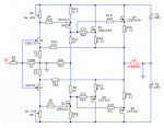
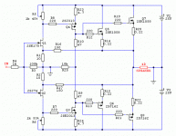
You have the another amplifier all mosfet amp. I attache the schematic. Hopefully soon I power up that.
any news
Attachments
Both this (Juma's ?LH)and the BA-2 amp have caps on the output. If you were to use a CCS over the VAS stage vs bootstrap CS, could these be eliminated? All components will be here today. I have 3, maybe 4 amps to build. F4, F5, BA-2, this one , Oh yeah , F3, R085 SRPP too. ANybody know a good marriage counselor?
Last edited:
Sorry about that, I don't know what happened , why so small.
I try again.
Greetings Gabor
Wonder how tha would sound X'ed?
Both this (Juma's ?LH)and the BA-2 amp have caps on the output. If you were to use a CCS over the VAS stage vs bootstrap CS, could these be eliminated? ...
Buzz buddy, there are many ways to change this amp. Feel free to experiment.
I made deliberate choices in this design in order to make it sound the way I want. You make it the way you like...
BTW, using CCS or bootstrap in VAS has nothing to do with the need for output cap. Split power supply does.
Last edited:
Juma,
I have more stupid questions. C3 and C19 do what? I would assume a coupling cap, but why is c19 not electrolytic? The output fets are both receiving their signal from the drain of Q2, correct? Also, the only feedback from output pair is through bootstrap CS? Isn't P2 setting gain independant of output feedback.
I have more stupid questions. C3 and C19 do what? I would assume a coupling cap, but why is c19 not electrolytic? The output fets are both receiving their signal from the drain of Q2, correct? Also, the only feedback from output pair is through bootstrap CS? Isn't P2 setting gain independant of output feedback.
C3 is there to equalize the AC potential at the gates of Q3 and Q4. C19 is a gentle slow-down compensation, you can leave it out if you want.C3 and C19 do what?
Becouse 120pF electrolytic capacitor doesn't exist.why is c19 not electrolytic?
From Q2 collector - BJTs don't have drain.The output fets are both receiving their signal from the drain of Q2, correct?
No, negative feedback loop consists of R13, R2, C10/C17. C9/C15 create (together with R8, R10) bootstrap arrangement which loads the Q2.Also, the only feedback from output pair is through bootstrap CS?
No. It sets the Vgs of Q3, Q4.Isn't P2 setting gain independant of output feedback.
Negative feedback doesn't work the way you imagine. To simplify it to the max., it compares the output signal to the input signal of the amplifier. There's a lot of stuff to read on this subject all over the net, just take your time...
C3 is there to equalize the AC potential at the gates of Q3 and Q4. C19 is a gentle slow-down compensation, you can leave it out if you want.
OK.
No, negative feedback loop consists of R13, R2, C10/C17.
C9/C15 create (together with R8, R10) bootstrap arrangement which loads the Q2.
Recognized the feedback to input device, just didn't know what role, if any the secnod stage played into it other than just being included in the loop. I get the bootstrap thanks to BA and Wiki, but wasn't sure if it just improved current source, or did something else?
It does play into the gain of the circuit, correct? I see how the overall gain is set by feedback, but some of the gain that is thrown away by feedback is created by q2, correct?No. It sets the Vgs of Q3, Q4.
Negative feedback doesn't work the way you imagine. To simplify it to the max., it compares the output signal to the input signal of the amplifier. There's a lot of stuff to read on this subject all over the net, just take your time...
Like Op Amps or....Transistor Man from All About Electronics
Not improved, but rather primitive current source. It's dynamic impedance is lower, so Q2's gain is lower than with standard CCS....wasn't sure if it just improved current source, or did something else?
No, no, no - you can't create a feedback node at BJT's collector - please read how the BJT works...It does play into the gain of the circuit, correct? I see how the overall gain is set by feedback, but some of the gain that is thrown away by feedback is created by q2, correct?
...Can i vary the Cap values. ...
Of course you can. Put two 220uF capacitors in parallel connection instead of one 470uF and you'll be fine

- Home
- Amplifiers
- Pass Labs
- 25W Class A amp with Lateral MOSFETs


 Can i vary the Cap values. I have lots of 220uF and .22 caps and didn't know if the 470 and .47 values were flexible.