Sorry thimios, Its was a deal, done already, a sponsored project. So no PCB here.
Sadface!
Sadface!
Member from post # 196 might have something to cheer you up
")
Last edited:
Sorry thimios, Its was a deal, done already, a sponsored project. So no PCB here.
Never mind prasi,we can't do everything
Hi
For the power supply, would a Meanwell LRS-350-36 (adjusted to 39.6Vdc) be OK ? In my opinion, SMPS normally do a fine job when powering class A amplifier. (Like the ACA)
The possible issue I see is the supply doesn’t seem to be double insulated (DC output floating). Since this amp is powered at -40 Vdc, could I still use this supply?
Any thoughts on this..?
Thanks
Eric
Hi
For the power supply, would a Meanwell LRS-350-36 (adjusted to 39.6Vdc) be OK ? In my opinion, SMPS normally do a fine job when powering class A amplifier. (Like the ACA)
The possible issue I see is the supply doesn’t seem to be double insulated (DC output floating). Since this amp is powered at -40 Vdc, could I still use this supply?
Any thoughts on this..?
Thanks
Eric
They are great. The only reason why they are not used more widely is the old-fashioned mindset that is so hard to change. But, they do sound great.
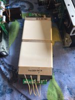
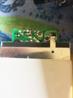
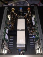
I have attached a few photos. You'll see that the metal shield is used as a connection (connector) between the mains supply earth, and the DC negative rail (DC return rail). This connection can be "lifted" at either end. So, for example, one could use two SMPS and make + and - 24V DC "symmetrical" supply.
I tested the ACA Meanwell; it had a sag of 100mV only, at 4A continuous draw, with minimal noise - exceptional.
The fan noise could be a problem; the ACA SMPS does not have it.
But to answer your question, yes you can use the SMPS if you can disconnect the mains ground connection from a DC supply return. Then DC + is a common, DC - is.... well it is minus and you can connect it wherever you want.
Attachments
Last edited:
Sorry Prof but I don't do debates. It tends to go down the wrong hole. I just share nice, simple, DIYer-friendly stuff that's well documented elsewhere and easily researchable. So if you want more, do it yourself. Don't be - or be if you like (it's up to you) lazy.
Best regards
Best regards
@ Juma:
Sir Juma, I am terribly sorry you mistook my request as indicative of downright laziness. I am NOT asking you to do my work for me because of my laziness. There are circuit surgeons and then there are poor hangers on like me who would like to try things with the help and approval of knowledgeable designers like you.
My request was very clear. I quote:
"...I had seen a similar 'positive ground' approach long back while trying out a Power Follower by Andrea Ciuffoli -- which I had thought sounded better than the "standard version" with a negative ground.
( http://www.audiodesignguide.com/my/Follower_99c.gif )
May I request you to go into some detail regarding the advantages of this topology and why you chose to opt for this approach, surely in the interests of better sound. (Mr Ciuffoli speaks of the decoupling of the signal currents from the power supply etc, which goes above my head.)..."
Surely you need not go into a debate to justify one or the other topology, which I know you dislike to do. Kindly enlighten us with some basic explanations to help our understanding.
Please also see if you could find the time to "re-do" the original circuit of yours in Post #1 in this new format; it would then be easy for us 'lazybones' to try and compare it with the original build.
It was this interest and enthusiasm that prompted me to make a request to you. Absolutely no intention of burdening you, sir, to whom we all owe a lot for all the simple and great-sounding designs you have given us over the years.
Perhaps now that the misconception is removed (hopefully!)you would think of spending some time to help us out.
As always, with warm regards.
@ Juma:
Sir, first off, my humble thanks for the prompt response.
I understand the point about the power supply being a short circuit (so much for the 'no caps' gang!).
I had on many occasions (right from the very early days of 3-4 W amplifiers using quasi-complementary germanium power output transistors) opted to have a series pair of electrolytics across the single rail supply and connect the speaker to the centre point. I haven't yet done any serious subjective evaluation of the arrangement though.
As for the Ciuffoli power follower, various friends had similar followers and I too had built one. Somehow there emerged a consensus that the positive earth version was the winner. I recalled this when I saw your JFET version implementation (Post # 180), and hence the queries and request for your help.
Thanks certainly for your willingness to help.
@ Mr Pass:
Sir, you mean to say that the deciding factor is power supply rejection? I can't recall if that aspect had come up during the evaluation of the Ciuffoli follower, in our case; we all had thought there was some 'magic' in the earthing choice!
Most of us here would like to "tap your brain" regarding borderline questions like this. Perhaps you would be kind enough to share more information. And also guidance about "converting" a negative earth circuit to a positive earth one--I assume attention has to be paid primarily to bypassing to 'earth'. I am no expert, but it would be a learning experience to follow practices that (often ignored in the commercial design space) might contribute to better sound quality, subjective and/or measured.
Warm regards to all.
Last edited:
Yes, that's about it, which side of the circuit has the poorest PSRR.
In the case of a single-ended SIT operated in Common Drain mode it is
particularly critical, as the SIT's Drain impedance is quite low, and noise
will go right through to the output. For this reason the SIT-3 which uses
an N channel SIT follower has the supply as negative with respect to
ground. The alternative would be to regulate the supply or cascode the
SIT or do something else altogether.
Thank you Mr Pass for that valuable pointer.
As a curious nitpicker, I would like to ask, is it just the noise, or is it something more...
Would it be possible for you to spend some time offering guidance on "converting" a negative earth circuit to a positive earth one easily...the pitfalls one has to watch out for etc; for the non-specialist who understands schematics and basic principles, that is.
Thank you, and warm regards.
Prof:
You have spent a great deal of space on this forum asking first Juma, and now Nelson Pass for detailed tutorials on how to build amplifiers. So far there is little evidence that you have spent an equal effort in trying to educate yourself. May I suggest that you buy a copy of The Art of Electronics by Horowitz and Hill and read all of the chapters regarding analog devices and circuits. Then build another basic amp or two. This is a journey that can be rewarding if you make the investment.
If this is beyond your means or capacity, it might be time to choose another hobby.
is it just the noise, or is it something more.
Would it be possible for you to spend some time offering guidance on "converting" a negative earth circuit to a positive earth one easily
Any noise or variation in the Drain to Source voltage of a fet carries both noise and distortion effects - unless the Drain impedance of the fet is
infinite, which it is not.
As to the conversion, you replace all V+ labels with Ground labels and
all Ground labels with V-. Then you reverse capacitor polarity for those
electrolytics where the voltage has any reference to Ground, including input and output caps.

The Prof,
in a sense, questions are more important than answers. Answers generate new questions so there is always a surplus of questions. The only way to arrest this upward spiral is to stop thinking.
This JLH inspired design cries for a huge, heavy, bulky (choke regulated) power supply and is tricky to implement properly. I question whether you are ready for it. What parts do you have in hand?
- Home
- Amplifiers
- Pass Labs
- 25W Class A amp with Lateral MOSFETs