We require a pic of the finished design with leds glowing.
.
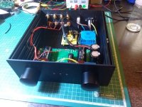
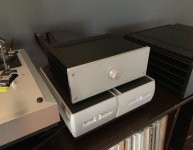
Here it is, finished it over the easter holidays. Still have to pimp up the front panel, I´ll post some more photos as soon as I'm done with that. It sounds fantastic and expect it to sound even better once is broken in. Thanks to Mr. Pass for this amazing gift, and thanks to every one for all the help!
Attachments
Gentlemen,
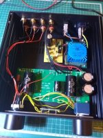
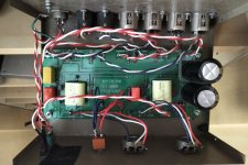
just finished my B1 - connected it up - Glorious!
Then: snap crackle pop - static in L channel only - leading to much reduced volume and much distortion - left channel only. After about 2 hours on. turned it off , let cool overnight - same story today.
Looked for cold solder joins - found 2 possible in left channel - same story.
Using remote regulated 18v supply - looks good. 17.85v - this supply has worked faithfully for several years on another pre-amp w/ no problems. So I don't think this is the problem.
XLR in/out connectors - no intermitents evident
separate L/R volume - doesn't seem to be crackle on pot.
L channel only - so I am guessing the onboard psu is ok.
I think I have attached a photo of layout.
Thanks for your help !
MG
Attachments
general remarks - use finer wire, less critical soldering
input switch - small toggle one - they're extremelly sensitive to heat , so soldering them is sure thing only if you're old shark
test it , if nothing else - with small crocs between contacts
all in all - your soldering looks lousy ; all you need is mileage
spending few hours worth of time on ootoobe soldering vids can't harm either
The switch bypass was unsuccessful. No change. Changed the input capacitors - no change
Re- soldered FETs I maybe some improvement - still some intermittent crackers but less and maybe improving as it continues to warm-up/break in.
Seems to be something with the FETS - I'll let it continue till it goes one way or the other, still ONLY left channel.
Any other ideas ?
Thanks
Re- soldered FETs I maybe some improvement - still some intermittent crackers but less and maybe improving as it continues to warm-up/break in.
Seems to be something with the FETS - I'll let it continue till it goes one way or the other, still ONLY left channel.
Any other ideas ?
Thanks
First DIY project – B1
Hi. This is my very first post, and build! I've nosed around the forum for a while, and it's nice to be able to actually provide some content of my own.
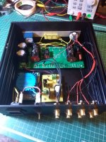
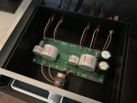
I recently tackled the B1, and sourced the board and FETs from PassDIY. I was happy to receive both a really nice board and NOS Toshiba 2SK170's! I went with the Galaxy 2U chassis, which was also impressively made.
I know Nelson set this up with two inputs, a switch, and two volume pots. My system is dedicated to vinyl and only has to handle a single input, so I streamlined and dropped an input. Likewise, I decided to stick with a 2 gang potentiometer and drop the second pot. In retrospect, I kind of wish I'd consider the dual pots more seriously, as I do like the idea of managing each channel separately. Either way, the single volume pot fits my goal of streamlined and simple, so I'm satisfied. At some point I may look at an Elma A47 for volume control.
For parts I stuck with Vishay Dale resistors, and splurged on Mundorf EVO Oil for the 1uF and 10uF caps. The big 15KuF are Nichicon. All the internal wiring was done with Neotech 23AWG solid silver. RCA connectors are Vampire CM2FCB, and the volume pot is a PEC 25k carbon log-taper.
Aside from a power jack I'm waiting on and a solder joint I need to clean up, it's complete! I'm loving everything about it so far!!
Huge thanks to Nelson for answering my novice questions!
Hi. This is my very first post, and build! I've nosed around the forum for a while, and it's nice to be able to actually provide some content of my own.
I recently tackled the B1, and sourced the board and FETs from PassDIY. I was happy to receive both a really nice board and NOS Toshiba 2SK170's! I went with the Galaxy 2U chassis, which was also impressively made.
I know Nelson set this up with two inputs, a switch, and two volume pots. My system is dedicated to vinyl and only has to handle a single input, so I streamlined and dropped an input. Likewise, I decided to stick with a 2 gang potentiometer and drop the second pot. In retrospect, I kind of wish I'd consider the dual pots more seriously, as I do like the idea of managing each channel separately. Either way, the single volume pot fits my goal of streamlined and simple, so I'm satisfied. At some point I may look at an Elma A47 for volume control.
For parts I stuck with Vishay Dale resistors, and splurged on Mundorf EVO Oil for the 1uF and 10uF caps. The big 15KuF are Nichicon. All the internal wiring was done with Neotech 23AWG solid silver. RCA connectors are Vampire CM2FCB, and the volume pot is a PEC 25k carbon log-taper.
Aside from a power jack I'm waiting on and a solder joint I need to clean up, it's complete! I'm loving everything about it so far!!
Huge thanks to Nelson for answering my novice questions!
Attachments
Thanks! I learned a lot and ended up with a functioning piece of gear – that's definitely a win/win for meCongratulations!
I've got the bug and am already trying to scope out my next project. I have an Aleph 30 and part of me wants to give the Aleph J a shot, since I have a good baseline for comparison. Probably a little ambitious on my part though. Might shoot for a headphone amp or Zen variation.
Welcome to the addiction. Beautiful build for a first time novice! And great components too. How does it sound?I'm loving everything about it so far!!
Thanks! It's certainly taken my system up a notch sound-wise! I'd been using an iFi iTube buffer while I decided what direction to take on a more permanent solution, and the B1 is a massive improvement over the iFi in every way. The top-end clarity is much better, but no 'etchiness' and it sounds very natural. Transients seem to be more noticeable now, again sounding very natural and adding some depth to the sound stage. Bottom-end is superb and has a nice, tight presentation.Welcome to the addiction. Beautiful build for a first time novice! And great components too. How does it sound?
I'm really happy with it!
Hello, I stupidly burned the jfets of my B1 buffer
(Reverse polarity on a lead-acid battery)
Is the LSK170 quad grade B (from diy audio store) a good choice?
The documentation states that Idss should be between 5 and 10 milliamperes.
... and Grade B Idss ranging from 6.0-12.0mA
Is this however OK. Or should i buy a new pcb with jfets from Pass diy
?
Thank you
component tweaking
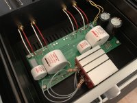
Recently added a Khozmo shunt attenuator, with great results. Have been swapping Vishay z-foil and Audio Note NM Tantalum as fun a/b exercise. Same with the power caps (leaning toward Nichicon Gold Tone). Oh, and I scorched my 10uf Mundorf with a soldering iron... No damage, just to my ego and ocd
Recently added a Khozmo shunt attenuator, with great results. Have been swapping Vishay z-foil and Audio Note NM Tantalum as fun a/b exercise. Same with the power caps (leaning toward Nichicon Gold Tone). Oh, and I scorched my 10uf Mundorf with a soldering iron... No damage, just to my ego and ocd
Attachments
Hello, I stupidly burned the jfets of my B1 buffer
(Reverse polarity on a lead-acid battery)
Is the LSK170 quad grade B (from diy audio store) a good choice?
The documentation states that Idss should be between 5 and 10 milliamperes.
... and Grade B Idss ranging from 6.0-12.0mA
Is this however OK. Or should i buy a new pcb with jfets from Pass diy
?
Thank you
I probably have no business answering this, but if It were me I’d spend the extra $10 and get the extra b1 board and Toshiba’s. That said, I believe the LS quad matched option would work just fine, and if you don’t want the extra board it saves you $10.
No damage, just to my ego and ocd
Maybe cover the scorched area with white hobby paint
Maybe cover the scorched area with white hobby paint
ah, good call!
I probably have no business answering this, but if It were me I’d spend the extra $10 and get the extra b1 board and Toshiba’s. That said, I believe the LS quad matched option would work just fine, and if you don’t want the extra board it saves you $10.
Hi,
Hi, thank you for your advice ;
I will probably buy the original kit at 'Pass DIY' to take advantage of the Toshiba JFETs NOS ...
... even if the shipping costs are horribly expensive !!
I really love the sound and neutrality of this device
it could be interesting to make 2 buffers with: 1.Toshiba 2.Linear Systems And compare them subjectively...
- Home
- Amplifiers
- Pass Labs
- B1 preamp build thread