Please remember that the input is a TWO (2) wire connection. Input connects to CW and to CCWI have a doubt concerning the wiring of the pot.
My Khozmo attenuator has the following marking: IN-OUT-GND.
I think to solder:
IN to CW
OUT to W
GND to CCW
Is it right?
The output is also a TWO wire connection. Output comes from W and CCW.
Do not break any of those 4 wires. All are needed to pass the signal from the source to the receiver.
Thanks.it seems ok
Please remember that the input is a TWO (2) wire connection. Input connects to CW and to CCW
The output is also a TWO wire connection. Output comes from W and CCW.
Do not break any of those 4 wires. All are needed to pass the signal from the source to the receiver.
But those connections are made on the PCB, no?
I just wanted to find the relation betwwen what is written on the PCB (C-CC-CCW) and what is written on my attenuator (IN-OUT-GND) to connect it like on the picture below:
Sorry.
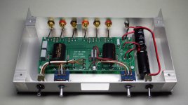
It's made using the PassDIY boards. Here are some pictures:
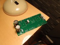
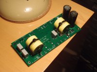
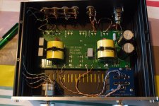
The problem I have is that the sound is weak and distorted on the right channel.
Test I've made:
-using an other input: same problem
-inverting left and right channel at the input: problem stays on the right channel
-inverting left and right channel at the output: problem goes on the left channel
-inverting left and right channel on the attenuator: problem stays on the right channel
So I think there's something wrong after the attenuator. I don't know if there's some voltage to check what's wrong (when working on my Pearl 2, I found a schematic with some voltages but I can't find such a thing for the B1).
It's made using the PassDIY boards. Here are some pictures:


The problem I have is that the sound is weak and distorted on the right channel.
Test I've made:
-using an other input: same problem
-inverting left and right channel at the input: problem stays on the right channel
-inverting left and right channel at the output: problem goes on the left channel
-inverting left and right channel on the attenuator: problem stays on the right channel
So I think there's something wrong after the attenuator. I don't know if there's some voltage to check what's wrong (when working on my Pearl 2, I found a schematic with some voltages but I can't find such a thing for the B1).
Last edited:
Just tried it: Problem stayed on the same channel.
Don't if it can help: I tried to listen the right channel (the problematic one) alone. I have to turn the pot to 2 or 3 o'clock to have a good sound volume, but the sound is awful ad there are some loud noises ("pop", "boom" or things like these).
Don't if it can help: I tried to listen the right channel (the problematic one) alone. I have to turn the pot to 2 or 3 o'clock to have a good sound volume, but the sound is awful ad there are some loud noises ("pop", "boom" or things like these).
Last edited:
Please remember that the input is a TWO (2) wire connection. Input connects to CW and to CCW
The output is also a TWO wire connection. Output comes from W and CCW.
Do not break any of those 4 wires. All are needed to pass the signal from the source to the receiver.
you have twisted the wires going to the attenuator incorrectly.View attachment 656537
The problem I have is that the sound is weak and distorted on the right channel..............
the Attenuator should have an input pair running from CW and CCW
And then an output pair running back to W and CCW.
You have twisted W and CW together and left the Signal Return separate from both.
you have twisted the wires going to the attenuator incorrectly.
the Attenuator should have an input pair running from CW and CCW
And then an output pair running back to W and CCW.
You have twisted W and CW together and left the Signal Return separate from both.
Hi Andrew. Thanks for your help.
I'm not sure to understand correctly what you mean. Sometimes, pictures make things easier to understand, so let's go.
Here is the wiring I've done:
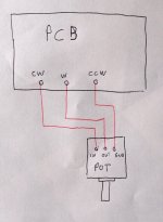
IN connected to CW
OUT connected to W
GND connected to CCW
Here is your solution, if I understand it correctly:
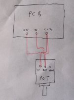
IN connected to CW and CCW
OUT connected to W and CCW
(I haven't drawn any connection to GND because you don't talk about it, but I presume there's one.)
There are two things I don't understand:
-When I look to the pictures of B1 made by other people, I can see that they have only 3 wires from PCB to potentiometer.
Some examples:
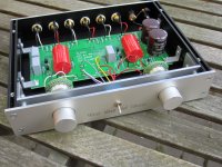
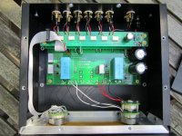
-The left channel works perfectly. If the wiring was wrong, both channel should have the same problem, no?
Or am I missing something?
Regards.
The twisting, or non twisting may have nothing to do with your problem. (but the capacitive coupling between the high level output wire and the lower level input wire may affect the two channels differently).
Your first pic omits the twisting of the signal Flow/Hot Input wire and the signal Flow/Hot Output wire.
Your drawing is NOT what you built.
The connection from the Output of the B1 is a TWO wire connection from CW and CCW. These are the two that should be a coaxial cable or a twisted pair cable.
These connect to IN and GND of one channel of the vol pot.
The output of the Vol Pot is W and GND. This is also a two wire connection and can be a coaxial or a twisted pair. This TWO wire pair goes to the B1 Input where it connects to W and CCW.
When you have these two sets of two wire connection completed you will realise you have duplicated the CCW wires. There are two on each channel. This creates a loop which will pick up interference. But the interference on the very small loop in the small signal (attenuated) route has been lessened and overall the two twisted pairs (or two coaxials) will give a cleaner signal.
Do not just copy other folks work unless you have proved to yourself that it is better than all other methods. There are thousands of Members on this site that do not understand that current flows around loops and that ALL current that leaves a Source MUST RETURN to that Source. Current does not Flow out along a single wire. A single wire is a broken connection.
Last edited:
I'm sorry.The twisting, or non twisting may have nothing to do with your problem. (but the capacitive coupling between the high level output wire and the lower level input wire may affect the two channels differently).
Your first pic omits the twisting of the signal Flow/Hot Input wire and the signal Flow/Hot Output wire.
Your drawing is NOT what you built.
I use twisted pairs from a Cat5e cable to make my wiring beause it's easy to work with, but if IN and OUT cables are twisted, that's mainly by chance.
Well, it's a wrong layout, if I understand you correctly.
I think I begin to understand what you're explaining, but I'm not sure.The connection from the Output of the B1 is a TWO wire connection from CW and CCW. These are the two that should be a coaxial cable or a twisted pair cable.
These connect to IN and GND of one channel of the vol pot.
The output of the Vol Pot is W and GND. This is also a two wire connection and can be a coaxial or a twisted pair. This TWO wire pair goes to the B1 Input where it connects to W and CCW.
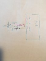
Is this drawing right?
Do not just copy other folks work unless you have proved to yourself that it is better than all other methods. There are thousands of Members on this site that do not understand that current flows around loops and that ALL current that leaves a Source MUST RETURN to that Source. Current does not Flow out along a single wire. A single wire is a broken connection.
When you're a beginner like me, you have no choice but to look at what other people do and follow their examples. That's what I did when reading 6L6's tutorial. That's what I'm doing when I follow Zenmod's and your explanations to help me to solve my problem.
If the drawing above is corresponding to what you mean, I'll try it tonight.
I'm sorry.I didn't draw the wiring with the cables twisted because I didn't know it was that important. I realise this was a mistake.
I use twisted pairs from a Cat5e cable to make my wiring beause it's easy to work with, but if IN and OUT cables are twisted, that's mainly by chance.
Well, it's a wrong layout, if I understand you correctly.
I think I begin to understand what you're explaining, but I'm not sure.
Is this drawing right?
View attachment 656812
When you're a beginner like me, you have no choice but to look at what other people do and follow their examples. That's what I did when reading 6L6's tutorial. That's what I'm doing when I follow Zenmod's and your explanations to help me to solve my problem.
If the drawing above is corresponding to what you mean, I'll try it tonight.
Just a beginner here too, nothing twisted, dead quiet and works perfectly.
Russellc
Attachments
Last edited:
One crosses (or appears to) on one side a little differently than the other. This messed me up first initial wiring attempt. I usually have all neatly twisted, but did not here. This was my second diy Pass project after F5. Not twisted, I dont know if its because of no gain or what, but it is silent as the grave. So I never "fixed" it.
Russellc
Russellc
Last edited:
check those few resistors values
check all solder joints
check proper position of JFets (N where N goes , P where P goes)
Tonight, I unsoldered all the resistors on the right channel and checked their values. They were OK.
I checked the solder joints, reworked some of them.
Concerning the J-Fets, I followed the drawing on the PCB to install them, so I presume it should be OK.
Unfortunately, I still have the same problem on the right channel.
I haven't tried Andrew's idea concerning the potentiometer wiring because I'd like to be sure that I understood correctly what he explained to me before making a mistake.
I think I have 10µF MKP somewhere, I could try one instead of the Auricap...
swap JFets between channels ..... that's all is left to do
or test suspicious ones (search for JFet matching - all you nee is 9V battery or something like that)
wire twisting and pairing is not in any way connected with your issues
more or less hum is completely another coin ....... and mentioning that now is of great help , obviously
or test suspicious ones (search for JFet matching - all you nee is 9V battery or something like that)
wire twisting and pairing is not in any way connected with your issues
more or less hum is completely another coin ....... and mentioning that now is of great help , obviously
- Home
- Amplifiers
- Pass Labs
- B1 preamp build thread
![20180114_123347[1].jpg](/community/data/attachments/610/610366-ce317ddd9f3c8281685842c85cb9fe01.jpg)