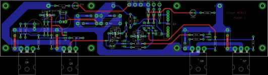
Questions: What is the reason for the parallel resistors r5/r6?
That is R5 4K75 in original scheme. I read in Aleph J thread that this poor resistor dissipates 380mW. In my simplified ltspice CCS experiment (which could have errors) it dissipates 318.5mW. Still a lot. When I start my first layout ever last year, ZM suggest to make it two 10K resistors. They will form 5K in parallel. Board could fit resitors like Dale RN60 /CMF60. Togeter they will dissipate the heat no problem.
To make a 1/2W 5K resistor, it appears...

That is R5 4K75 in original scheme. I read in Aleph J thread that this poor resistor dissipates 380mW. In my simplified ltspice CCS experiment (which could have errors) it dissipates 318.5mW. Still a lot. When I start my first layout ever last year, ZM suggest to make it two 10K resistors. They will form 5K in parallel. Board could fit resitors like Dale RN60 /CMF60. Togeter they will dissipate the heat no problem.
Ok that make sens. Maybe I should build a simulation and observe a little bit more, still a newbie at understanding circuit..
Another question
 What about c5 c6? I know they were not in the original design and I have read somewhere that if they were to update the store board they would delete those. What have convince you to put them in ?
Ok that make sens. Maybe I should build a simulation and observe a little bit more, still a newbie at understanding circuit..
Me too.
Another question
In short. Better sleep.
Also found interesting links from neighbour threads:
1. http://hifisonix.com/wordpress/wp-content/uploads/2019/02/Ground-Loops.pdf
2. http://hifisonix.com/wordpress/wp-c...B-Design-Guidlines-for-Minimizing-Hum-1-1.pdf
Article "More Guidelines for Minimizing Amplifier Hum", page 8.
If I understand it correctly (and I am not 100% sure) those 0.1uF film caps could help trap HF current on amplifier board.
5p is most likely necessary, so called Lag Cap, anti-oscillation thingie
without that one, most amps are becoming anti-social thingies, itself
other one is bypass cap for Aleph CCS modulation, in my book also necessary one
Oups my mistake, I ment c6 c7. Thank you for all your answers guys.
Rainfallsky, i think it’s clear that I can not help that much with the pcb design but i could certainly help with the beta testing when everything is ready. I assure you my assembly skills are much better than my circuit understanding skills
I have a question about Voltage/Speaker inputs/outputs.
Right now those pads have hole pattern for Fast-On blades.
1.4mm holes dimension and 5.08mm between holes.
Should I add a hole in between for say AWG 16 cable?
What are the max conductor dimensions of a stranded AWG 16 cable?
Fast-On blade still would have better overall contact place.
Right now those pads have hole pattern for Fast-On blades.
1.4mm holes dimension and 5.08mm between holes.
Should I add a hole in between for say AWG 16 cable?
What are the max conductor dimensions of a stranded AWG 16 cable?
Fast-On blade still would have better overall contact place.
Attachments
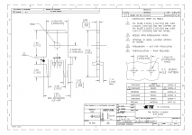
OK, I have something screwed up and would appreciate another set of eyes taking a look.
I'm attempting to build Aleph J with the SemiSouth devices generously donated by Mr. Pass.
I'm using the DIYAudio store boards. Populated as per original schematic except deleted Q6, R17, Q8, R12 and Q3, R13, R14.
R16 is .24/5W Q5 is IRFP240. Q7 is E120R100
Using J74 as LTP. Q2 is ZTX550 and Q4 ZTX450. I've re-checked the pinouts.
Voltage across R8 is 8.3V across R7 is 1.4V and across R9-Q5-R16 is 4.7V
Bias across R18 is .35V
The problem is that the offset is 19 V (not mV). I can adjust using R7 but the bias voltage rapidly increases. R27 seems to have no effect on bias.
I'm sure this must be something obvious and I've looked several times but can't find it. I've read hundreds of the pages of the Aleph J thread and all the pages of this thread(Aleph J with Semisouth). The answer may be in there but I can't find it.
So it will be helpful to have another set of eyes.
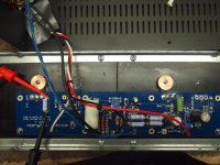
Schematic and photo attached.
Thank you for your time and assistance.
I'm attempting to build Aleph J with the SemiSouth devices generously donated by Mr. Pass.
I'm using the DIYAudio store boards. Populated as per original schematic except deleted Q6, R17, Q8, R12 and Q3, R13, R14.
R16 is .24/5W Q5 is IRFP240. Q7 is E120R100
Using J74 as LTP. Q2 is ZTX550 and Q4 ZTX450. I've re-checked the pinouts.
Voltage across R8 is 8.3V across R7 is 1.4V and across R9-Q5-R16 is 4.7V
Bias across R18 is .35V
The problem is that the offset is 19 V (not mV). I can adjust using R7 but the bias voltage rapidly increases. R27 seems to have no effect on bias.
I'm sure this must be something obvious and I've looked several times but can't find it. I've read hundreds of the pages of the Aleph J thread and all the pages of this thread(Aleph J with Semisouth). The answer may be in there but I can't find it.
So it will be helpful to have another set of eyes.
Schematic and photo attached.
Thank you for your time and assistance.
Attachments
Look where R11 goes.
Yeah, looks like you’ll want to jumper the collector of empty q3 to The top of R12.
looking what you crossed in schm, everything done fineOK, I have something screwed up and would appreciate another set of eyes taking a look.
I'm attempting to build Aleph J with the SemiSouth devices generously donated by Mr. Pass.
I'm using the DIYAudio store boards. Populated as per original schematic except deleted Q6, R17, Q8, R12 and Q3, R13, R14.
R16 is .24/5W Q5 is IRFP240. Q7 is E120R100
Using J74 as LTP. Q2 is ZTX550 and Q4 ZTX450. I've re-checked the pinouts.
Voltage across R8 is 8.3V across R7 is 1.4V and across R9-Q5-R16 is 4.7V
Bias across R18 is .35V
The problem is that the offset is 19 V (not mV). I can adjust using R7 but the bias voltage rapidly increases. R27 seems to have no effect on bias.
I'm sure this must be something obvious and I've looked several times but can't find it. I've read hundreds of the pages of the Aleph J thread and all the pages of this thread(Aleph J with Semisouth). The answer may be in there but I can't find it.
So it will be helpful to have another set of eyes.
Schematic and photo attached.
Thank you for your time and assistance.
though, if you have positive offset, that means lower mosfet ( SS) is still closed, insufficient positive voltage at gate, ref. to source
with smaller source resistor in Aleph CCS , R27 value need to be substantially smaller than in case with original 0R47 in place of source resistors (Q4 asking that it's base is at ~0V65 more positive than it's emiter, for its duty)
first solve that, limiting current there ( say 10-15K) , then go further
you'll most likely need little more than 1V4 across R7 too, so if there is 1V4 with trimpot maxed, put 330R in series, or use next value of trimpot
Excellent. That gives me some more options to try. Thank you.looking what you crossed in schm, everything done fine
though, if you have positive offset, that means lower mosfet ( SS) is still closed, insufficient positive voltage at gate, ref. to source
with smaller source resistor in Aleph CCS , R27 value need to be substantially smaller than in case with original 0R47 in place of source resistors (Q4 asking that it's base is at ~0V65 more positive than it's emiter, for its duty)
first solve that, limiting current there ( say 10-15K) , then go further
you'll most likely need little more than 1V4 across R7 too, so if there is 1V4 with trimpot maxed, put 330R in series, or use next value of trimpot
On my board, R11 is connected to R12 and that is connected to drain of Q1A of the LTP. I think this trace is hidden in the photo shown by Rainfallsky
Got a photo of a boards backside.
Yes those are connected. Sorry.
The cause is somewhere else.
9.1 V zener in D1
Okey. That must be big 5W zener or higher.
I am out of obviuous ideas..
OK, I think it's solved. Started R27 at 13k ohm and was able to adjust bias to .35V and offset to about zero. I guess I should not have been afraid to try R27 potentiometer from end to end adjustment. duh...

- Home
- Amplifiers
- Pass Labs
- Semisouth Aleph J?