Those very small sinks are sufficient for a quick test run only. Got to eventually mount the Mosfets to the chassis. I suggest you do that right from the start not to desolder & resolder them. Because clip on or side sinks vs floor are different mounting styles. Floor wants the Mosfets soldered underside the board edges.
Those very small sinks are sufficient for a quick test run only. Got to eventually mount the Mosfets to the chassis. I suggest you do that right from the start not to desolder & resolder them. Because clip on or side sinks vs floor are different mounting styles. Floor wants the Mosfets soldered underside the board edges.
Will do so!
Thank you, Salas
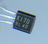
I‘ve got these jets, labeled «F170 B4D»
Are they good for the b1 ?
I bought them back in April as one of my first attempts of parts-sourcing.
Now I doubt I got some whatever-parts. The look quite good, but by looking at the label, are they grade D? I measured as in Transistor matching, result is 0.23 - 0.24 mA
thank you.
david
Where did you buy them from?
From Toshiba datasheet:
IDSS classification GR: 2.6~6.5 mA, BL: 6.0~12 mA, V: 10~20 mA
Either you made error in measuring or they are fakes.
Based on the image these should be BL grade - 6.0-12 mA
I had no Idea where to get good jets (or what to look for, found them @ Studio Electronics, Burbank CA...
They look as good ones, but I can't say more. (I'm also wondering what the BL 4D means... there seem to be other 'codes' around.)
The measurement was my first attempt, using a 9V (8.5V actually), one run according to the link mentioned above, the 2.3 mA came out with a 100Ohm resistor (according to NP(?)).
Will try with a batch of DIYAudiostore matched pair... and prepare myself to get back to the store for another run.
The link you reference doesn't show a measurement resistor - it shows the current being measured as through a meter.
If you put a resistor in the circuit then you would measure voltage across the 100R resistor (100 ohm) and then you should see V and use V=IR to calculate I.
Someone can correct my math but I think you should see a voltage reading in millivolts that you can multiply by 100 to get Idss in mA ...
Note that this is not going to give you Idss that you can match with other people's results but it will give you the ability to compare jfets with one another for matching within your own batch and should give you an idea of whether or not it's absolutely fake or falls within the expected range.
I‘ve got these jets, labeled «F170 B4D»
Are they good for the b1 ?
I try to come along with this, but it‘s hard to find information about all of this.
(I'm also wondering what the BL 4D means... there seem to be other 'codes' around.)
Is this a picture you took? If yes, the external clues are right for genuine. The extra characters are IDSS class and batch code. Still do test for IDSS.
If its not a picture you took, take a macro one and post it here. There is no genuine starting with F. Starts with K for Toshiba or with LS on top left, then below it has K170 etc. for Linear Systems.
Salas,
Yes, these are mine.
Now have to find out if/what's wrong with the measurement.
Thank you for clarifying the batch code.
david
Salas,
Yes, these are mine.
Now have to find out if/what's wrong with the measurement.
Thank you for clarifying the batch code.
david
I have found out that I bungled. With or without the jfets, measurements are the same across the wires. Positive 1.96 mA / -1.18 mA. ha-ha-ha.
But I don't know yet what the mistake is.

Attachments
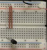
Where is the resistor?
Twichie and DougL‘—in this run, I sticked (or believed so)
 to the schematic displayed below. This is according to Transistor matching as above...
Next run will be with resistor, but I want to dig out the reference...
Don't use long wires. Short Fet pins 2,3 with a small jumper locally. Connect battery minus there. Set DMM to mA range, stick red probe's banana plug to the DMM's special mA input. Touch red probe to battery plus. Touch black probe to Fet's pin 1. You should see IDSS displayed.
Don't use long wires. Short Fet pins 2,3 with a small jumper locally. Connect battery minus there. Set DMM to mA range, stick red probe's banana plug to the DMM's special mA input. Touch red probe to battery plus. Touch black probe to Fet's pin 1. You should see IDSS displayed.
Salsa, thank you. Sorry for bothering you and clogging up the thread.
I'm at home, "no solder"-zone
,but computer is ok. So I did this simulation.
did I interpret it correctly?
thank you!
Attachments
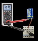
It looks OK
*Take care not to short B+ by touching wrong pins during tests because the DMM's internal mA input fuse is going to blow. And its a special safety spec expensive one. In proper meters at least.
*Before you will note down IDSS let it run for a minute to settle. Stick each Fet on paper and write the mA figure next to it for future reference if you got many pieces.
- Home
- Amplifiers
- Pass Labs
- Mezmerize DCB1 Building Thread