@ Meper You can get an "potentiometers extension kit", or build one your self with parts from the bay..
Drill hole in front panel, pillow block with set screws, to hold extension rod in place, bolted to the back of the front panel, rod with coupling one end,potmeter mounted on angle braket, volume knob other end
Use these search words at the bay, and you should get the idea..
Pillow Block Bearing Flange
Stepper Motor Coupler Connector
bearing block
Smooth Rod Steel Linear Rail Shaft
cnc copling
Is it a "press fitting" of ball bearing into the front panel and 6mm shaft into the ball bearing?
Press fit on shaft and a slide fit into the housing.
Thank you!
I took the easy solution and ordered a 3 mm front panel so I can mount the attenuator directly on the panel. I can see that depending on the distance to the PCB there can be a technical advantage in having a long shaft to the attenuator so wires will be as short as possible.
I took the easy solution and ordered a 3 mm front panel so I can mount the attenuator directly on the panel. I can see that depending on the distance to the PCB there can be a technical advantage in having a long shaft to the attenuator so wires will be as short as possible.
Hi All,
I just powered on a moderate hotrod version, 2X20 Ohm resistors per side, and my voltage across these resistors is 10V. Way too high. Input voltage is 17V AC. Channel voltage is 10.58 and 9.99 and the offset is 0.7 and 0.1 mV. Everything should be matched, but I could have gotten something mixed up after testing. I can already see some slight discoloration in the input resistors, so before I power it back on to take additional measurements I'd appreciate any input.
Thanks!
Joe
Attachments
No, the rails voltage won't change much. Its rigged to mismatch their DC so*. You could mutually swap the two signal JFETS in the 0.5mV channel to have a minus reading as in the other channel. If you want to be perfectionist that is. A minus means their two IDSS are in the right order i.e. the top FET isn't marginally saturated by the bottom one (top & bottom when schematically speaking). Performance wise it does not have an impact when so well matched already.
*If you want to even that out as its already a feature in the 10 Years After Edition PCB see about doing the "leg trick" in your earlier edition: https://www.diyaudio.com/forums/the...ezmerize-b1-buffer-preamp-21.html#post5406253
*If you want to even that out as its already a feature in the 10 Years After Edition PCB see about doing the "leg trick" in your earlier edition: https://www.diyaudio.com/forums/the...ezmerize-b1-buffer-preamp-21.html#post5406253
Is this a Khozmo kit or your own invention with ball bearing in the front panel?
I need to find a solution for the 10mm front panel I have for the BA-3 pre. The easy solution would be to just get a 3mm panel and mount the attenuator as usual.
A little late, but I found that the extender kit from PartsConexcion worked great on the 10 mm panel.
Russellc
Thank you!
I took the easy approach and ordered a 3mm front panel!
It plays very well. Now I just need to adjust the distortion…….I will "play" with that in the near future. Now P3 is just set to center position.
I have no hum and that is good. Noise is also low. So I guess I did something right with how the ground wires are connected etc......even with relative long twisted signal wires it works.
Attachments
How do I check my JFET's idss for this project?
Once I get the testing completed I can start building the DCB1.
I have what is suppose to be Toshiba 2SK170BL's and Linear's LSK170A's.
I'm not sure which brand/version will be best to use in the DCB1.
Thanks for any help.
Once I get the testing completed I can start building the DCB1.
I have what is suppose to be Toshiba 2SK170BL's and Linear's LSK170A's.
I'm not sure which brand/version will be best to use in the DCB1.
Thanks for any help.
Last edited:
Use the BLs for the quad and the As for the PSU section. Both are good FETs it's just their different IDSS classes are better to be distributed that way in the DCB1.
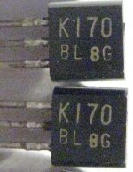
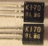
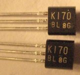
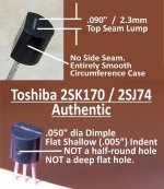
For the Toshiba BLs post a close up picture of one in case you suspect fakes. We are usually able to tell.
As for measuring IDSS see this link: Transistor matching - JFET
For the Toshiba BLs post a close up picture of one in case you suspect fakes. We are usually able to tell.
As for measuring IDSS see this link: Transistor matching - JFET
Hi salas,
Thank you for the link.
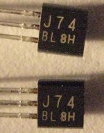
Here's a few photos of the Toshiba LSK170-BL's that I recently purchased and also a photo of LSJ74-BL's that I purchased at the same time.
Some of them have a visible line over top of the number 8 and some don't or either they faded over time.
What is the meaning of the line?
Do they look like real Toshiba's?
Thanks.
Thank you for the link.
Here's a few photos of the Toshiba LSK170-BL's that I recently purchased and also a photo of LSJ74-BL's that I purchased at the same time.
Some of them have a visible line over top of the number 8 and some don't or either they faded over time.
What is the meaning of the line?
Do they look like real Toshiba's?
Thanks.
Attachments
") .
.Pass DIY Addict
Joined 2000
Paid Member
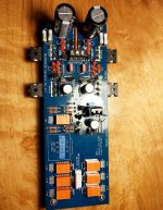
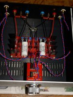
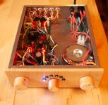
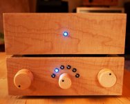
Finally finished my Mez that I started building 3 years ago right before moving and starting a PhD. How naïve. But now I'm writing a dissertation and procrastinating hard with some DIY audio. Shown with my JFET Phono stage in the second pic.
Sounds great no matter what I plug into it. Thanks all.
Sounds great no matter what I plug into it. Thanks all.
Attachments
- Home
- Amplifiers
- Pass Labs
- Mezmerize DCB1 Building Thread