I'll give it a go and run continuity checks to make sure there aren't any cracks. Given that it will be in a preamp that should rarely ever move, I should be OK.
SjoerdSmits- Are you talking about taking three strands out of CAT7 and braiding them together? I was thinking of doing that but thought that, for some reason, people frown on a two-signal/one return braid vs. two twisted-pairs. A braid would make it easier to mount three wires in the PCB.
Out of curiosity, why was this PCB made with only one return mount on the PCB and not one for each channel?
Don't braid. That increases the loop area. Increased loop area increases the inductance and thus increases interference.
A twisted pair is low loop area. Two twisted pairs reduces crosstalk. (all the CAT cable have 4 twisted pairs carrying different signals on each pair and they have adequate crosstalk rejection upto very high frequencies).
I think a twisted, or braided, triplet risks increased crosstalk.
One could use a pair of coax for the two signals and conjoin the shields/screens where they meet up with the commoned signal return pad.
But you must keep the two coax screens VERY close coupled to reduce interference on the signal return, that will get into the wanted signal. This close coupling of the signal returans ALSO applies to the two twisted pairs alternative.
Last edited:
Well, I think I'll try two twisted pairs, and wrap/solder the return together and then attach to the PCB, doing my best to minimize and loops and to keep things as close together as possible. With only one return pad, I think that's the best I can really hope for. I'm probably overthinking this but better to work it out now then to try to track down problems later.
Problems about matching SK170BL
Recentliy I have bought a batch of SK170BL. My intention was to use this for my Mezmerize build.
For matching I always follow what is suggested on the diamondstar site, using 9V power so the Idss can be read directly on my multimeter.
The "new" SK170 behave very different from from an "old batch" of this Jfets that I bought serveral years ago.
I also have an ordinary trasistor tester that I can use for a kind of dobbel "control".
This is the measuring results on one of the "new" SK170BL:
With the diamondstar test upset: Idss=18mA
With my trasistor tester: At 1.3mA the Vgs=896
The same test with some of my "old" SK170BL:
With the diamondstar test upset: Idss=7.76 mA
With my trasistor tester: At 0.58mA the Vgs=330
All my "old" Jfets have worked perfect (with J74) in serveral F5 builds, so nothing wrong with them.
But what can be said about all the "new" SK170 BL?? Are they all fake and usless for my Mezmerize build??
Genuine SK170BL is difficult to find. Is there any newer alternatives, and where can I if neccesary buy this?(not from China I guess)
Eivind S
Last edited:
The max Idss @ 10Vds is 12mA for bl grade. V grade maxes @ 20mA and you're not far short of that.
18mA can't be right, if your measuring correctly.
Measure Vp using >=1M to limit Id to ~0.1uA (=1Vrs)
Then use Borbely to calculate gm.
Of course there is a newer and still current alternative.
LSK170b for the three devices (per channel) that need high gm and low Vp.
All the other jFETs can be low gm and high Vp.
Read the Thread.
Last edited:
Thank you Andrew. If all the "new" SK170 show up to be V grades and not BL, can I use them in my Mezmerikze build for the six SK170(three per channel) that are not marked as BL, but marked as "not matched"?
Together with the SK170 (not BL I now understand) I also bought SJ74 and they all measured an Idss between 8 and 9 mA with P=9V.
Eivind S
Together with the SK170 (not BL I now understand) I also bought SJ74 and they all measured an Idss between 8 and 9 mA with P=9V.
Eivind S
I'll bet they are not 2sk170v.
They will be low gm high Vp fakes.
They will be low gm high Vp fakes.
measure Vp and calculate gm.I also bought SJ74 and they all measured an Idss between 8 and 9 mA with P=9V.
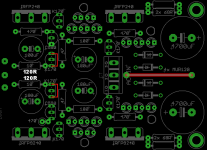
When there is a problem with sourcing good semis you may test an alternative I just thought for you regarding the Mez PSU section. Use Fairchild PF5102 (currently in production) for all the JFETs except those two next to the 10R resistors places. You omit those two JFETs. You jumper their outer pads instead with short wires and you use 120R instead of 10R next to them. The resistors value change is mandatory, not something to be left for later. 100R is acceptable too. Don't try other random values. See attachment.
Attachments
Salas: To be sure that I do not misunderstand: The Fairchield PF5102 are subsitutes for the SK170 in the PSU section only? The SK170 BL that are noticed to be matched, should they still be the "real thing" or is there some subsitutes to be used for them as well.
I still have some of my "old" and real SK170 BL left, but since I am building as much as four(4) Mezmerize, I will be in shorts of SK170 BL. I will use this four Mezmerize as buffers before the amplifiers in my 4-way active speakers.
Eivind S
I still have some of my "old" and real SK170 BL left, but since I am building as much as four(4) Mezmerize, I will be in shorts of SK170 BL. I will use this four Mezmerize as buffers before the amplifiers in my 4-way active speakers.
Eivind S
Salas: To be sure that I do not misunderstand: The Fairchield PF5102 are subsitutes for the SK170 in the PSU section only? The SK170 BL that are noticed to be matched, should they still be the "real thing" or is there some subsitutes to be used for them as well.
I still have some of my "old" and real SK170 BL left, but since I am building as much as four(4) Mezmerize, I will be in shorts of SK170 BL. I will use this four Mezmerize as buffers before the amplifiers in my 4-way active speakers.
Eivind S
Yes, substitutes for the PSU area only. Going along well given you will also perform that specific simple mod I attached. Don't worry when you will see in the datasheet that they are not pin compatible, because due to the way they are connected in the specific circuit positions the G-S or S-G pin order amounts to the same result. The audio signal path "JFET quartet" should be the real thing or the Linear Systems clone. LSKs are on the diyaA Store but graded not matched. Andrew used to have some LSK matches I think, not sure if anymore, ask him. There is also one ebay guy "alweit" from Israel that people say has genuine matched pairs. I don't know if Tea-Bag could also help you out, ask him.
Despite Andrew's warning of using a braid, I've done so very successfully with no ill affects in my Light-Dependent Resistance (LDR) volume control here. Remember, for very short runs of signal wires this will usually work with fine results. For more critical application, or longer internal runs, I prefer very small coaxial cable....SjoerdSmits- Are you talking about taking three strands out of CAT7 and braiding them together? I was thinking of doing that but thought that, for some reason, people frown on a two-signal/one return braid vs. two twisted-pairs. A braid would make it easier to mount three wires in the PCB...
Years ago I was building a project that called for some RG-174/U. I bought a roll and since I've started building audio projects, it seems to work very well where I need better shielding for longer runs of signal wire. It may be overkill for audio, but I have lots of it!
") It is super small diameter (1/8"), very flexible (26AWG) so it can be tucked away in tight spaces very easily.
It is super small diameter (1/8"), very flexible (26AWG) so it can be tucked away in tight spaces very easily. Rick
Hi All,
Thanks everyone who helped me to troubleshoot my dcb1 build. I have finally had a chance to test it with a power amplifier directly and it has shown no oscillation.
So the problem was when using line in input of audiolab only.
Thanks everyone for the help and all suggestions
Sent from my ONE A2003 using Tapatalk
Good news. It maybe had seen some extra capacitance or something to that specific input. Don't mod it with higher output resistor than 220R if its not you must often pair it with the audiolab. Much resistance damping is not helping the SQ except where strictly necessary for good working order.
Here is my first message on this board, troubleshooting the Mez.. I've seen similar questions before, but still don't get what to do
The 5 LED's on the plus side barely glow. Measurements:
Board voltage -10.5V / +8.9V
Across 2x68R: 3.55V om each side
Across 10R: 0.15V / 0 (zero)
DC offset 0.1mV / 0
Mosfets are equally hot on both sides. The amp does play music, although I did not get to judge how good it is yet
I did not match the LED's initially. Should I take them all out and resort? I have some spares to shuffle around if needed
Thanks for any help in advance
You don't need to match the LEDsHere is my first message on this board, troubleshooting the Mez.. I've seen similar questions before, but still don't get what to do
The 5 LED's on the plus side barely glow. Measurements:
Board voltage -10.5V / +8.9V
Across 2x68R: 3.55V om each side
Across 10R: 0.15V / 0 (zero)
DC offset 0.1mV / 0
Mosfets are equally hot on both sides. The amp does play music, although I did not get to judge how good it is yet
I did not match the LED's initially. Should I take them all out and resort? I have some spares to shuffle around if needed
Thanks for any help in advance
They each just drop some voltage and the string of LEDs drops a bigger voltage.
What voltages do you have at the AC input and at the DC input?
Welcome to the forums. Make sure that the 10 Ohm resistor on (+) side is 10 Ohm indeed first and not higher by mistake. Change the FET next to that 10 Ohm resistor if she is right.
It is 10 Ohm. I'll look for a replacement FET, thanks
Sent from my iPhone using Tapatalk
You don't need to match the LEDs
They each just drop some voltage and the string of LEDs drops a bigger voltage.
What voltages do you have at the AC input and at the DC input?
AC inputs are close to 12V, DC is around 17V
Voltage drop measured across the 5 LED strings on the board is 9.9V on negative side and 8.6V on plus side
Sent from my iPhone using Tapatalk
- Home
- Amplifiers
- Pass Labs
- Mezmerize DCB1 Building Thread