I am going to build a hotrod version by using two boxes one is for the transformer, so my problem is the way to transfer power AC or DC?
Using DC
transformer >>> rectifiers >>> a big cap of 22000uf (I have alot of them...cheap rubicon)>>> cable 1m >>> one 4700uf (or another one 22000uf?)>>> DCB1
Is this a good configuration?
thanks
yes, like AndrewT recommends, put rectifiers and at least one set of caps in the first box along with transformer.
Silver plated copper in teflon is nice. I have used it extensively and found it good for signal as well as output. I slightly prefer, slightly, a single strand of silver ( I use 28awg ) in some teflon tube for signal. Its not expensive like everyone on ebay seems to think it should be. Go google Myron Toback and he has 99.99% silver for really good prices. I think the last quote was 22USD per ounce and you can specify how soft/hard you want it. I have not yet used this for output wire as a friend sold me some of those Nordost flat speaker cables for pennies and I dont feel like changing just for the sake of a project right now.
Uriah
Uriah
Silver plated copper in teflon wire is going to be used as a powercord!
For internal wiring I also use 99.999% 0.4mm Solid Silver Wire Teflon PTFE Insulation
Connex Audio items - Get great deals on Analogue Interconnects, DIY Supplies items on eBay.co.uk Shops!
For internal wiring I also use 99.999% 0.4mm Solid Silver Wire Teflon PTFE Insulation
Connex Audio items - Get great deals on Analogue Interconnects, DIY Supplies items on eBay.co.uk Shops!
According to Farnell (the UK branch) the 12V OMRON relays are no longer available. They suggest this as an alternative:
NEC|EA2-12NU|RELAY, DPCO, 12VDC | Farnell United Kingdom
I assume this is fine for the Blue Mez boards?
- John
NEC|EA2-12NU|RELAY, DPCO, 12VDC | Farnell United Kingdom
I assume this is fine for the Blue Mez boards?
- John
A couple of clarification points if I may to ensure I have read and understood the circuit/pcb.
From what I can see there is no seperate signal ground output as per many of the chip amps, but instead signal ground simply joins to the centre tap and thus grounds that way. Is this correct? (it appears to be from looking at the circuit board).
If also assume I don't have to populate all of the selector relays if I don't need them all, correct?
Finally, where it says GND at the selector text then I assume all the input ground wires go to this terminal connection. This would seem logical and make sense to me.
Thanks
Another perhaps silly question, but one that is perplexing me, albeit I have come up with an answer in my own mind, but want to check.
The question is around how to wire the rotary switch for the relays.
With a non relay design then I'm comfortable with wiring the inputs to a rotary switch. However as the inputs from the RCA's are directly connected to the relays, the standard pole/way wiring will have to be different.
The solution as I see it is with the 2 pole/6 way switch is to have connections from each of pole A's "ways" connected to selector inputs 1-6, and have a ground wire from pole B connected the Grnd input of the selector.
Is that a sensible/working solution?
Thanks
I'm not sure I understand your description.
The relay needs a supply to pull in.
Take a supply from the regulated relay supply.
Attach this to the centre pole of the 6way switch.
Connect one of the switched poles to the relay coil pad.
The return route back to the supply is in the PCB routing.
This brings the relay supply through the switch to the relay coil and then back to regulator.
Each switched pole goes to a different relay pad.
Thanks Andrew.
I understand what you're saying, but am confused how that translates to the Mezmerize board.
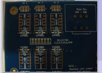
I've included an image of the area that is currently causing me confusion - the area on the board titled selector. How would I translate your explanation into wiring the rotary switch using the "selector" area on the board? Would I still need to take a feed from the 12V regulated relay supply (I'm using a 12V relay), connect that to pole A on the switch, and then run a wire from Way 1 to the input at selector 1, a wire from Way 2 to the input at selector 2, and so on?
If so, what is the purpose of GND in the Selector inputs? Each of the relays allows you to connect left and right "live" inputs from the RCA's, plus the "ground" from each of the RCA's. For example, IN 1 in the top left corner of the image has three through holes - one for the left input "live", one for the right input "live" and the third, middle one, connects to the centre tap connection via the PCB rails and a small jumper. This I have assumed is for the signal input grounds to go to earth.
Thanks
I understand what you're saying, but am confused how that translates to the Mezmerize board.
I've included an image of the area that is currently causing me confusion - the area on the board titled selector. How would I translate your explanation into wiring the rotary switch using the "selector" area on the board? Would I still need to take a feed from the 12V regulated relay supply (I'm using a 12V relay), connect that to pole A on the switch, and then run a wire from Way 1 to the input at selector 1, a wire from Way 2 to the input at selector 2, and so on?
If so, what is the purpose of GND in the Selector inputs? Each of the relays allows you to connect left and right "live" inputs from the RCA's, plus the "ground" from each of the RCA's. For example, IN 1 in the top left corner of the image has three through holes - one for the left input "live", one for the right input "live" and the third, middle one, connects to the centre tap connection via the PCB rails and a small jumper. This I have assumed is for the signal input grounds to go to earth.
Thanks
Attachments
Last edited:
Yes. It can bring somewhat lower voltages than average by not driving the LEDS as hard, but its of no real consequence.
Hi Salas,
For the unmatched 170's, if I use GR type, what are the better idss values? (I have a bunch over 5mA)
And for the matched 170's, I saw here that on this case you prefer the 7mA values over the 8 to 10mA values, but the build guide shows that the 8mA to 10mA values are the preferable, what is the right value?.
Best Regards
Use from your GRs those over 5mA so they turn on the LEDS good. We were getting many BL 8-9-10mA in batches back then and we put that in the BOM. Its not written in stone, 7mA will work as well only a little cooler and a bit less wilder for differences to find matching easier. Not really different, maybe a bit more easier for those having that region.
Next question, the BOM says a decoupling cap of 150nF is required next to the BC517, yet there is nothing on the board for this.
Where does it go? Is it in the space near to the BC517 marked 100uF, and if so why does the BOM say 5 x 100uF are required? If it isn't the 100uF slot, where does it fit?
Thanks
Where does it go? Is it in the space near to the BC517 marked 100uF, and if so why does the BOM say 5 x 100uF are required? If it isn't the 100uF slot, where does it fit?
Thanks
- Home
- Amplifiers
- Pass Labs
- Mezmerize DCB1 Building Thread