I'm going backwards, first built the circuit and then understand it.
In the end I found the BC-517. I have not tried the BC875.
These are the values obtained.
Offset: L (0,8 mV) R(0,4 mV)
+Vcc 10 V. -Vcc -9,5 V.
I was out of balance current 230-160 mA. and final voltage Vcc from 10 to 9.5 V.
I will change the resistance to equal both to 230 mA.
Current:I put 2x16 Oh. 5W. in parallel and 3x LED matched 5.3 V in both. But the IRFP240 is 4 V. and IRFP9240 is 3.5 V.
Voltaje: The 5X LED, both matched, not measure the same 8.9 and 9.3 mV. I do not know because. By circulating 6.4 mA. and 16 mA.?
I put other values measured in the circuit.
-Vcc -9,5 V.
160 mA. 8 Oh. 1,29 V.
IRFP240 (4 V.)
3xLED (7,4 mA.) 5,3 Vol
5xLED (6,4 mA.) 8,9 V.
+Vcc 10 V.
230 mA. 8 Oh. 1,84 V.
IRFP9240 (3,5 V.)
3xLED (7,9 mA.) 5,3 vol.
5xLED ( 16 mA.) 9,3 V.
Putting 5.3 Oh. equates current 230 mA. Same-Vcc and output offset.
-Vcc -9,5 V.
230 mA. 5,3 Oh. 1,22 V.
IRFP240 (4,14 V.)
3xLED (7,4 mA.) 5,3 Vol
5xLED (6,4 mA.) 8,9 V.
+Vcc 10 V.
230 mA. 8 Oh. 1,84 V.
IRFP9240 (3,5 V.)
3xLED (7,9 mA.) 5,3 vol.
5xLED ( 16 mA.) 9,3 V.
-Vcc -9,5 V.
230 mA. 5,3 Oh. 1,22 V.
IRFP240 (4,14 V.)
3xLED (7,4 mA.) 5,3 Vol
5xLED (6,4 mA.) 8,9 V.
+Vcc 10 V.
230 mA. 8 Oh. 1,84 V.
IRFP9240 (3,5 V.)
3xLED (7,9 mA.) 5,3 vol.
5xLED ( 16 mA.) 9,3 V.
Last edited:
I have this:
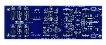
Buffer Mezmerize and SSL V1.1 Black in Back.to BuffaloDAC in one box.
I have Buffer 10 V and. -9.5 V (230 mA.).
0.8 mV and 0.4 mV offset.
I have 2 Hypnotize for a balanced versión in the future.
An externally hosted image should be here but it was not working when we last tested it.
Buffer Mezmerize and SSL V1.1 Black in Back.to BuffaloDAC in one box.
I have Buffer 10 V and. -9.5 V (230 mA.).
0.8 mV and 0.4 mV offset.
I have 2 Hypnotize for a balanced versión in the future.
From my little experience IRFP240 - IRFP9240, there is always an imbalance 0.5 V. or more.
I think your source would be more balanced if you put the negative current reference 3x yellow LED imbalance + 0.5 V., versus positive branch 3x red LED.
The same Mezmerize 5xLED voltage reference: negative branch 9,5 V. yellow LED, versus positive branch 9 V. red LED.
In SSLV1.1 Salas source and IRF610 - IRF9610 same thing happened to me:
-Vcc -15 V.
260 mA. 3 Oh. 0,8 V.
IRF610 (4,8 V.)
3xLED 5,6 Vol (3 mA.)
2xLED 3,6 V. (4 mA.)
+Vcc 15 V.
260 mA. 6,8 Oh. 1,7 V.
IRF9610 (4 V.)
3xLED 5,7 vol. (3 mA.)
2xLED 3,6 V. (4 mA.)
With this imbalance Vref would be used similar R for current.
- Vcc and Vcc would be similar as well.
Last edited:
There are the formulas in the guides for those who wanna be perfectly balanced for current (only aesthetically significant when near enough already, the gfs curves need more kick to really differ). PMOS & NMOS differ, even individual parts differ for Vgs. Using different LEDS instead of trimming the CCS set resistors is another valid way of course, correct. In the Mezmerize though, there will be always more current running through the positive Vref. It is designed in, that +/-Vo asymmetry helps offset and changes the THD profile towards 2nd harmonic, voicing it at low CCS. In the Hypno hot rod its symmetrical. If your goal is to compare, find the using the hypnotize as a power supply thread, there I show the ''leg trick'' for restoring current symmetry through the strings of 5 Vrefs. It has been referred enough times in the past. A couple did the mod but returned to the standard Mez Vref CCS config, but see for your self.
") Yes, your Mez looks finely set. Let us know how it went in the end.
Yes, your Mez looks finely set. Let us know how it went in the end.I have read other threads DCB1. I do not understand the differences between Mesmerize and Hypnotize about the imbalance of power output V. Could explain the differences in circuit components that affect it and how?
I worry about the imbalance of 5xLED. Ed Fontaine sold me two matched groups to 9.1 V. But very different 8.9 and 9.3 V measure . I fear that LED mix before welding. I have more LED and can do 5xLED other two groups with equal branch voltage positive and negative. Would that be necessary?
Thank you very much Salas, Ed LaFontaine, Tea-Bag, Russ White, and other participants, is an excellent work. 2 days listening Buffalo DAC with DCB1.
I think that distorts a little at maximum volume, I'll measure.
The scene , first day, was bad, I had to move speakers. Today sounds perfect with good center scene and more detail than my other DAC. The bass is different, more detailed timbre. And it sounds nicer and smoother.
The output of the DAC (IVY-III I / V Stage) with DCB1 has more body. Without DCB1 thin sound, is less impressive. DAC (Legato I / V Stage) the improvement is even greater, especially in bass.
Salas,
why is it necessary to undo your jFET wiring in the Mez when you told us how important that the Hyp must be done that way.
The only difference between Hyp & Mez is the option for upto 6 relay selectable inputs.
The buffer and PSU is identical on both implementations.
You have the option to ignore this post since I have already trawled through that Hyp wiring in previous posts.
I wrote it's not necessary (post 349), oneclock's Mez behaves rightly. I showed what is the difference there and how it can be done otherwise for evaluation because oneclock thought his leds could be different, and could not sum up the older posts. The black Hypno it is also done this Mez way. The hot rod Hypno is voiced a bit differently due to the high current being default, has 4 PSU filter caps, film vref cap, and its done the other way in the positive vref CCS detail.
Thanks Salas. It is hard to answer all threads and questions.
I guess that "solder G & S pins K170" what you meant ''leg trick''.
I haven´t found the thread where you said. I thought he had read them all. 'i will Review the thread Mezmerice as separate power supply again.
DCB1 be improved adjustment potentiometer + Vcc and-Vcc like SSLV1.1?
If you could see the output on a spectrum analyzer or distorsion meter, Could be adjusted to improve second and third harmonic for the FET or adjust the offset?
Davide, I have a small pop to turn DCB1 off.
The measurements are correct. No distortion at maximum volume. Contrary to how I thought.
The Buffalo at the exit of DCB1 has less distortion than without DCB1. Buffalo DAC direct output is 10 db further in the third harmonic that with DCB1. (impedance meter 200 KOh.). Buffalo also has lower intermodulation DCB1 through than without DCB1.
The output was some noise DCB1 AC (-110 dB) and I had to change the RCA output to the opposite end. Has decreased.
- Home
- Amplifiers
- Pass Labs
- Mezmerize DCB1 Building Thread