No, I ask Scott.
Patrick
The BF862 had a TO92 adaptor on it. On a pc-board I think up to 4 or so in parallel are stable. BTW I used a good SMT inductor not a bead. I'm also the wrong person to as about the sonic signature of components.

LSJ174 measurements
Here are some measurements on the Linear Systems replacement for the Toshiba 2SJ74. The top ones are from a noisey test batch and the bottom are good ones mixed with the Toshibas. Very useable devices and the DC parameters are pretty close. The second graph shows J74 versus some devices made for the nuclear detection industry. You can see .3 nV hz^-1/2 is nice and quiet.
Here are some measurements on the Linear Systems replacement for the Toshiba 2SJ74. The top ones are from a noisey test batch and the bottom are good ones mixed with the Toshibas. Very useable devices and the DC parameters are pretty close. The second graph shows J74 versus some devices made for the nuclear detection industry. You can see .3 nV hz^-1/2 is nice and quiet.
Attachments


I wonder which device you measured.
LSJ74 has been announced since 2006 but I have not seen it available on their website or at their distributors.
Maybe you are one of those with samples, but I have not seen production devices, apprently due to difficulties in meeting noise specs.
(LS)J174 is a "direct replacement" for the Siliconix J174, and has a much higher Idss than 2SJ74 :
http://www.linearsystems.com/datasheets/J174.pdf
Patrick
Yes they sent samples to Nelson and he put a few on my desk. They are very close to production on this part. Both batches work but one is slightly better, very close to the Toshiba 2SJ174. I am happy they have picked this up because Toshiba seems to have lost interest in audio parts.
With the supply of 2SK369's have pretty much dried out completely.
So we were forced to source 2SK372's as equivalent replacement.
Recently in a batch of 2SK372V's with "8J" date code, we observed something strange for devices with Idss > 20mA.
There is a noticeable change in slope of the Vgs curve at cuurent ~ 20mA
Looks like gate leakage ?
(We actually measured current at the source as the curve label says.)
Hope Scott & Co. are till watching,
Patrick
.
Attachments
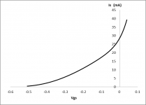
12V*20ma ,240mW, change in slope??2SK372 Maximum ratings..
Drain power dissipation PD 200 mW
Re. comparison of the 2SK372 and BF962, I am reading about 1.5dB better values for the 372 from the plots at the beginning of this post, which equates about a factor of 1.2; that compared to 70 versus 10pF of Ciss.
So, in a circuitry that requires paralleling of FETs and has to work from a higher input impedance, the 372 seems not to be the preferred choice (cascodes may help a little).
So, in a circuitry that requires paralleling of FETs and has to work from a higher input impedance, the 372 seems not to be the preferred choice (cascodes may help a little).
A somewhat different question for Scott and other experts.
Is there a simple method to measure Ciss and Crss of small signal JFETs ?
5~10% accuracy would be enough.
Thanks in advance,
Patrick
I haven't tried, I usually use a GR 4 wire bridge, not exactly economical. At home I use a B&K 875B hand held bridge, with taking care to zero you can do pretty well by averaging a few measurements on the 200pF scale. You can isolate and apply bias with a good cap and big R.
Well it is not quite as simple as hooking an LCR meter to the JFET pins.
Firstly you need to make sure the gate is negative biased enough to switch off the N-JFET completely (i.e. no Id).
Then you need to bypass the Cds such that it appears as a short during measurement.
And then you need to be sure the test voltage is small enough, like <<0.5Vrms.
And the test frequency not excessively high.
There are suggested test methods here:
http://literature.cdn.keysight.com/litweb/pdf/5992-0207EN.pdf
I tried it out in Spice with a 2SK170 but it does not give the value I was expecting.
So I still have to figure out what is not quite right .....
Hence the question.
Determining the capacitance itself is the easiest part.
Patrick
Well it is not quite as simple as hooking an LCR meter to the JFET pins.
Firstly you need to make sure the gate is negative biased enough to switch off the N-JFET completely (i.e. no Id).
Then you need to bypass the Cds such that it appears as a short during measurement.
And then you need to be sure the test voltage is small enough, like <<0.5Vrms.
And the test frequency not excessively high.
That's the nice thing about the GR bridge it is setup to do diodes with bias T's and variable excitation voltage built in. If it makes life any easier there is scant difference between Cgs and Cds at the same bias you could measure them together. You can extract information off of the C/V curves on the data sheet, it is ~V^.33. SPICE models with large differences are simply wrong. SPICE uses C at 0 volts and computes the right value.
Last edited:
- Home
- Amplifiers
- Pass Labs
- More FET noise measurements (for EUVL)