Only because of impatient people here who cannot wait until December, and already want to order things now.
Of course they may, but then I also don't want to be blamed that the case won't fit their GB components.
So a large case measuring so 500x500x200mm will fit anything.
")
Patrick
Of course they may, but then I also don't want to be blamed that the case won't fit their GB components.
So a large case measuring so 500x500x200mm will fit anything.
Patrick
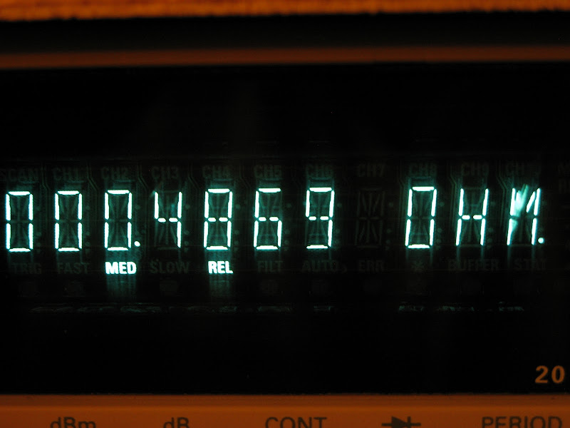
Just an update on resistors.
I managed to find some Futaba MPC71 5W 0.22 Ohm resistors in my parts box (basically the same as mpc74).
I tested them at both 1A and 2A and the performance is as good as two cpf3 3W resistors in parrallel.
just for fun I tried to matched some .47 ohm resistors. It looks like measuring current or voltage is perhaps the better way to group the devices, even with a high precision ohmmeter.
I think when it all comes down to it, either you don't bother as Patrick mentioned or you trim the resulting amp, as Zen Mod mentioned
Correct.
Making a larger case with large heatsinks to accomdate more dissipation will make is too expensive to make and to ship.
Then it is better to buy commercial ones.
You may consider putting the regulator device on its own free standing heatsink within the case.
There is not a lot of spcae, but you might manage.
If you allow 4V drop & 4A bias, total dissipation is 16W, so the free-standing sink has to be 2W/°C.
Something like
V 5512G Profilkühlkörper - reichelt elektronik - Der Techniksortimenter - OnlineShop für Elektronik, Netbooks, PC-Komponenten, Kabel, Bauteile, Software & Bücher - ISO 9001:2000 Zertifiziert
(75x50x25mm, not small)
Patrick
Last edited:
> It looks like measuring current or voltage is perhaps the better way to group the devices, even with a high precision ohmmeter.
> either you don't bother as Patrick mentioned
I do bother.
> you trim the resulting amp, as Zen Mod mentioned
That depends what you trim. You suggest trimming THD.
My approach is to trim second (and maybe third) harmonics without getting higher 4th, 5th, ....., before soldering.
If THD is the goal, then opamp and high feedback amp (like the Goldmund ?) rules.
No point going to Class A.
Patrick
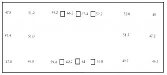
Finished testing of the MF35-151 heatsinks.
Air temperature was 22.1 degrees.
The small rectangles represent the position of mosfets across the heatsink.
Applied Voltages and Current were +/- 26.1V and 2.6A (135W).
Obviously between the mosfets the temperature is quite hot but further away the temperature drops off a fair bit. If there was a way to spread the heat across the heatsink better than we might be in busines.
Also, once the heatsinks are conected to the top and bottom plates and front and back plates the temperature will come down further.
Attachments
Last edited:
I haven't tested the MF35-151, but empirically it seems like it should be limited to 100W.
You might get a little lower temperatures if you were able to line the devices up 1/3 of the way up from the bottom six in a row, but I still don't you'll get comfortable temperatures at 135W without a fan.
You might get a little lower temperatures if you were able to line the devices up 1/3 of the way up from the bottom six in a row, but I still don't you'll get comfortable temperatures at 135W without a fan.
What happened to the approx. +30C over ambient "rule of thumb"? The "put your hand on it for at least 5 sec."? Personally I can hold my hand on 65C for minutes. It looks to me like the outer extremidies are about 55C. I agree speading the load is more effectively using the sink. Hence, I prefer the long board (DiyAudio boards) configuration myself.
Are you planing on 3 paralell pair in your F5?

Are you planing on 3 paralell pair in your F5?
Geez, flg, I thought my hands were numb.
With mica isolators you're at around 1.6 C/W junction to sink. At 22.5W per device on a 65C sink (at the device), that's right around 100C at the junctions. That should be OK, but most people will find your sinks way too hot to touch. Silpads will be a little higher thermal resistance and therefore higher junction temperatures.
With mica isolators you're at around 1.6 C/W junction to sink. At 22.5W per device on a 65C sink (at the device), that's right around 100C at the junctions. That should be OK, but most people will find your sinks way too hot to touch. Silpads will be a little higher thermal resistance and therefore higher junction temperatures.
Also, once the heatsinks are conected to the top and bottom plates and front and back plates the temperature will come down further.
I'm not sure about that. Once its connected together you will also see an increase in ambient temperature, that in my opinion, will negate whatever you gain by this adding more aluminum mass, even with agressive number of cooling holes.
Don't get too excited. Look at the measurement in detail.
The average temperature over the heatsink is 57°C. Minus 22.1, then divided by 135W gives 0.26°C/W.
And that is exactly according to Catalog (0.21 x 1.3 correction factor). So don't blame Conrad.
Our task is to spread the heat out evenly so that there is no 20°C over the area of the sink.
How, don't know yet. Give it time.
And you have to look at the entire picture -- what is the final junction temperature.
For those who cannot sleep because of this, you can read through this :
http://www.semicon.toshiba.co.jp/eng/shared/reliability_pdf/bde0128g_chap03.pdf
Or, order yourself a Hifi2000 today !!
Patrick
- Status
- This old topic is closed. If you want to reopen this topic, contact a moderator using the "Report Post" button.
- Home
- Amplifiers
- Pass Labs
- Balanced F5 question