Since quite a few of us will never have the opportunity to attend the burning amp festival. I thought it would be fun to have a simulation shoot out to promote some friendly competition amongst us fellow diyer's.
The rules are as follow.
The design is intended to be a preamp to drive F5 to full power.
Gain of the preamp is limited to 2x to 3x
The preamp is limited to a maximum of 2 stages. (if you can do it with a single gain stage even better)
No balanced or X circuits allowed
The design does not need to be original. You can use other peoples designs.
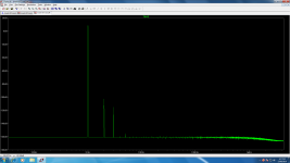
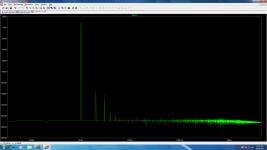
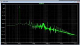
Performance is assessed by measuring fft of 4V peak into 100k load at 1000Hz.
May the best man/woman win.
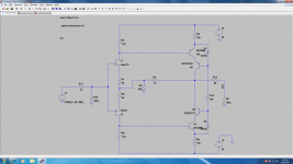
Ok here is my first attempt.
Remember this is meant to be fun. Definitely not intended to be taken seriously.
The rules are as follow.
The design is intended to be a preamp to drive F5 to full power.
Gain of the preamp is limited to 2x to 3x
The preamp is limited to a maximum of 2 stages. (if you can do it with a single gain stage even better)
No balanced or X circuits allowed
The design does not need to be original. You can use other peoples designs.
Performance is assessed by measuring fft of 4V peak into 100k load at 1000Hz.
May the best man/woman win.
Ok here is my first attempt.
Remember this is meant to be fun. Definitely not intended to be taken seriously.
Attachments
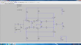
How about this one?
Once I have a few designs here I will build the top 3 designs, and do measurements in the lab to see how they compare to the simulations.
Then I will do listening tests to see if there is any correlation between labe results and listening tests.
I am a slow mover so it could be some time before I get around to doing this.
Attachments
Great Topic.
I've been wondering which is a good preamp, to match up with an F5.
Since a power supply is already in place, may as well add a preamp to make an integrated.
The F5 has only 15 dB's of gain, so I wonder if a follower design would work.
Any follower has a voltage gain of slightly less than 1.
Here is a cathode follower I've developed that uses a current source.
It seems to be very well behaved when powering up and down.
Not sure if the DC blocking cap is needed off of the cathode.
.
Attachments
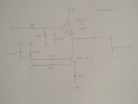
Maybe I should explain this circuit a bit more.
A number of people have used the B1 buffer with the F5 Amp.
The B1 is a source follower, with a constant current source.
However, I would like a tube in the integrated, so the n jFET in the B1 was replaced with a triode, and the current source was changed.
I tested the cathode follower, with a triangle wave generator, and the linearity is quite good.
I have not tested the overshoot or settling time, however, since there is no Feedback, its probably good.
As I recall, a 6922 requires a 90 Vdc plate voltage, but works just fine with 24Vdc and a constant current source.
The tube was biased at around 10 mA = Vbe / 68 ohms
Using an oscilloscope, to look at the emitter side of the 68 ohm resistor, shows the current source is quite good.
However, the 100nF ceramic cap is needed to increase the stability of the current source.
The DC blocking cap is needed before going to the F5 Amp.
In the end though, the question is how does this unit sound with the F5 Amp ?
Would the combination be too transparent ?
Attachments

Last edited:

don't waste your time with under-voltaged tubes
give them proper voltage and current and they'll shine - in this way - 6922 is drek.
Thanks for this info.
The linearity of the cathode follower circuit looks great with a scope - but how does it sound is the question.
I really don't want to get into high voltage power supplies - also, I'd like to use the F5's power supply which is already in the box.
How do low voltage tubes sound ?
Have you heard a 12AE6, 12U7 or 6GM8 ? Any good ?
I see 12ae6's and 12u7's are quite inexpensive - but the price of 6gm8's - ouch !
Sorry to side track things a bit.
Last edited:
The rules are as follow.
The design is intended to be a preamp to drive F5 to full power.
Gain of the preamp is limited to 2x to 3x
The preamp is limited to a maximum of 2 stages. (if you can do it with a single gain stage even better)
No balanced or X circuits allowed
The design does not need to be original. You can use other peoples designs.
Performance is assessed by measuring fft of 4V peak into 100k load at 1000Hz.
Some simple questions for clarification of the rules:
-is 4V the amplitude or the peak-to-peak value (i.e. the corresponding amplitude is 2V) ?
-the THD is computed from how many harmonics ?
Some more complex questions:
-how is a stage defined ? Is there a limit on the number of transistors in a stage or in the whole circuit ?
-is global negative feed-back (GNFB) allowed ?
... -is 4V the amplitude or the peak-to-peak value ...
It's 4V peak or 8V peak-to-peak.
Last edited:
Thanks for this info.......
use appropriate part for given conditions
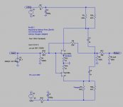
SLCF with semiconductors
Jfet as main element , any sort of CCS ( I like two bjt version - ) as load , and either bjt or mosfet cascode
properly executed , SLCF is pretty invisible soundwise , no matter which parts are used
or just make complementary Jfet follower
Attachments

Zen, as I said on other forum you can`t adjust the offset this way - (changing jfet`s Vds)

So how do you suppose to fix the dc offset?
NS
hey Canaman,
Looks good,all of them sound a little better with a few beers,lol.It's the special ingredient,lol.
Cheers my friend!
NS
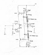
My candidate, attached. After a few cold Foster's, it sounds great. (I cheated--more than 2 gain stages....!)
Looks good,all of them sound a little better with a few beers,lol.It's the special ingredient,lol.
Cheers my friend!
NS
- Status
- This old topic is closed. If you want to reopen this topic, contact a moderator using the "Report Post" button.
- Home
- Amplifiers
- Pass Labs
- F5 Preamp Simulation Shoot Out