Every thing I have learnt has come through trial and error based on ideas from Nelson Pass, Erno Borbley, Joe Curl, and everyone here.
Sorry John.
Will do.
I am willing to try anything.
I am also about to try different levels of capacitance smoothing in the power supply. I have a stack of 33000uF caps ready to be utilised.
So I am planning on seeing what audible differences I might hear going from 33000uF per rail per channell all the way up to 198,000uF per rail per channel (in increments of 33,000uF for each test).
While I admire the spirit to experiment, I cannot quite understand the purpose of the added complexity.
Is there a reason why you would want to put a diff pair at the frontend ?
Do you get better distortion spectrums by doing so ?
Patrick
PS Of course you would expect me to say that if you do want a balanced version of the F5, then there is already one -- published, built, by tested by at least 2 DIYer's other than the publisher.
Last edited:
Will do.
I am willing to try anything.
I am also about to try different levels of capacitance smoothing in the power supply. I have a stack of 33000uF caps ready to be utilised.
So I am planning on seeing what audible differences I might hear going from 33000uF per rail per channell all the way up to 198,000uF per rail per channel (in increments of 33,000uF for each test).
Yes that might be interesting. We know that increasing the cap value will sucessively increase the high-order noise and supply harmonics on the supply line. Be curious whether you would hear that.
jd
While I admire the spirit to experiment, I cannot quite understand the purpose of the added complexity.
Is there a reason why you would want to put a diff pair at the frontend ?
Do you get better distortion spectrums by doing so ?
Patrick
PS Of course you would expect me to say that if you do want a balanced version of the F5, then there is already one -- published, built, by tested by at least 2 DIYer's other than the publisher.
No reason really for the added complexty, except to learn, and try new things.
The simulated distortion is virtually identical (with 6V peak into 8Ohms), using the exact voltages and bias current for each amp (ie +/-25V, 2.2A). I tested the original F5 in the lab and it performs brilliantly. I have not tested the differential version in the lab.
The reason I have not tried the F5X is that my speakers are 4Ohms. Will 4Ohms be a problem?
Also I do not have a DAC with balanced out. Will using a single ended to balanced converter give the same benefits as a DAC with balanced outputs?
thanh,
Keep up the good work, experimenting, I have found that is the best way to learn.
From what I gather Patrick's balanced F5 is the cat's meow. At some point I will have to build one and I might cascode the front end. Maybe he will share more of his experiences with his design.
Jam
Keep up the good work, experimenting, I have found that is the best way to learn.
From what I gather Patrick's balanced F5 is the cat's meow. At some point I will have to build one and I might cascode the front end. Maybe he will share more of his experiences with his design.
Jam
I thought it was 8-10V? UURGHI thought the sweet spot for the jfets were 18 to 24 Volts

No reason really for the added complexty, except to learn, and try new things.
The simulated distortion is virtually identical (with 6V peak into 8Ohms), using the exact voltages and bias current for each amp (ie +/-25V, 2.2A). I tested the original F5 in the lab and it performs brilliantly. I have not tested the differential version in the lab.
The reason I have not tried the F5X is that my speakers are 4Ohms. Will 4Ohms be a problem?
Also I do not have a DAC with balanced out. Will using a single ended to balanced converter give the same benefits as a DAC with balanced outputs?
Simulation. Well, I'm sure you've read all kinds of stuff about that... The truth is: Do your models have the same parameters as actual devices in your box of goodies? Or, Nelsons recomended/measured parts? My JFET models have something like 11mA Idss for 1 and I don't remeber the other but it isn't normal? I forgot the mS figure but I remeber it's bogus for real devices too. If you don't modify those parameters, among others, your sim will not produce real life results... This is one of those cases where you are relying on N.P.s real world stuff and the sim is to general in character to replicate that behaviour... Just my 2cents. But, I'm just a dog. UURRGH
Oh well I will just have to do real world testing of the differential version to compare it against the original.
In the end I am not too concerned about distortion measurements, as long as the amp produces a nice clean square wave and there isn't any large amounts of 5th order harmonic then I am happy.
I think there is a lot to be gained by paying attention (and money) to the power supply.
This is where I think I will make the greatest improvements.
Also Jams suggestion of playing with the cascode to alter the voltage across the jfets could be interesting also.
I am also keen on trying out 2sk2013/2sj313 as Juma has suggested (but I will have to drop the supply down to 24V)
If only semisouth or Nelson made complementary power jfets.
you can make it with dual differential , but that way it's not F5 anymore , but just one of many similar minimalistic amps
So a dual differential based amp is more minimalist than a F5 ?..
The reason I have not tried the F5X is that my speakers are 4Ohms. Will 4Ohms be a problem?
My F5X drives a pair of Dynaudio Contour S 1.4 which have a minimum impedance lower then 4Ohm without any problems.
Also I do not have a DAC with balanced out. Will using a single ended to balanced converter give the same benefits as a DAC with balanced outputs?
For converting the single ended signal from my Sony CDP337 I use a slightly modified version of an UGS with well matched SK2013/SJ313 instead of IRF610/9610 and JFETs with Patrick's fabulous TO92 heatsinks.
Regards, Uwe
Attachments
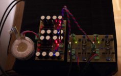
> For converting the single ended signal from my Sony CDP337 I use a slightly modified version of an UGS with well matched SK2013/SJ313 instead of IRF610/9610 and JFETs with Patrick's fabulous TO92 heatsinks.
Uwe,
You will even get better tracking if you couple the two heat sinks on one channel to each other. The simplest way is to arctic-silver a piece of aluminium to bridge the gap. The best way is to send me the dimensions and we'll custom make a few pieces for you. I would say around USD10 a piece (for 4 JFETs) because of small quantities. Standard type 2 are now 3USD a piece (for 2 JFETs).
Patrick
PS to complete the job, you should really also use a heatsink to couple ALL the TO220 devices.
Last edited:
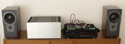
Uwe,
..................more photographs please.
Jam
Hi Jam,
here you will find some more photos from my F5X and of course some listening impressions.
http://www.diyaudio.com/forums/pass-labs/121228-f5-power-amplifier-566.html#post1973964
In the meantime I've changed the toroids to more powerful ones and of course I drilled a hole in the front panel for a blue LED
")
Regards, Uwe
Thanks
Do you have a schematic of you UGS?
Hi Thanh,
here is the actual schematic.
Regards, Uwe
Attachments
- Status
- This old topic is closed. If you want to reopen this topic, contact a moderator using the "Report Post" button.
- Home
- Amplifiers
- Pass Labs
- Modified Dual Differential F5