Would you mind sharing the files for that board? Was going to look into cost of getting them made.
Thanks!!!
Hi Naz, I don't really feel right about distributing the gerbers etc., but if the boards work after I build mine, I should have a few left from a minimum order. If you are still interested then I can send you a set of boards for cost + shipping.
Chas
Hi Naz, I don't really feel right about distributing the gerbers etc., but if the boards work after I build mine, I should have a few left from a minimum order. If you are still interested then I can send you a set of boards for cost + shipping.
Chas
Please add me to the list of people interested in buying a set of the boards.
Thanks,
Will
Wow, time flies when you're having too many projects to count...
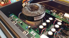
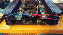
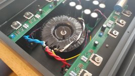
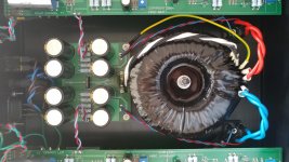
It's been over 1 1/2 years since I wanted to change the humming power transformer of my F1J, and today I finally got around to doing it. Two weeks or so ago, I ordered a toroidy 600VA 2x115VAC -> 2x18VAC audio grade toroidal, which arrived two days ago.
Yesterday evening was spent with getting the old transformer unstuck from the silicone compound that coupled it to the chassis. Today, in went the new donut.
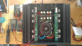
I'm glad to report that everything seems to be working as I had hoped for. Voltages and offsets all within specs, and the hum is gone too. Can't wait to get around to listen to it, and luckily there's a weekend with lots of rain coming up")
It's been over 1 1/2 years since I wanted to change the humming power transformer of my F1J, and today I finally got around to doing it. Two weeks or so ago, I ordered a toroidy 600VA 2x115VAC -> 2x18VAC audio grade toroidal, which arrived two days ago.
Yesterday evening was spent with getting the old transformer unstuck from the silicone compound that coupled it to the chassis. Today, in went the new donut.
I'm glad to report that everything seems to be working as I had hoped for. Voltages and offsets all within specs, and the hum is gone too. Can't wait to get around to listen to it, and luckily there's a weekend with lots of rain coming up
Attachments

Pass DIY Addict
Joined 2000
Paid Member
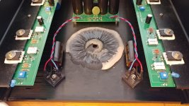
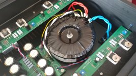
The caps right at the rectifier bridges are the same as the ones in the PSU, they're all Nichicon UKW 22000uF 25V types. Post #106 shows a little more detail.
The idea is the following:
With the outboard rectifier bridges and all that class A current draw, there usually are large current pulses between the bridge output and the first PSU filter cap. In terms of magnetic stray fields, this connection, which is of substantial length, is supposedly the one radiating the most since it carries the largest current variations. A big fat cap right at the bridge should make things more smooth and thus reduce electromagnetic pollution inside the chassis.
Valid assumption or not, I ordered ten caps due to the volume dicount offered, so I thought I migh as well use them
Edit: ZM, I keep noticing that we're often answering the same questions, wherein I usually go into long-winded rants, and your replies are usually short and right on point
Last edited:
Pass DIY Addict
Joined 2000
Paid Member

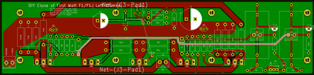
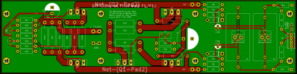
After taking a break for a while, I have made some more progress on my PCB layout for the F1 and I am hoping for some input. I have maximized the power traces and ran them on both sides of the board where possible. I am wondering about the incoming signal trace that runs the length of the board (highlighted in pink in the image below). Will this trace be likely to pick up noise because of its length? Any other suggestions/concerns?
Thanks!
Thanks!
Attachments
Just curious, why not use the existing F1 circuit board layout as a basis? The artwork has been published on page 8 of the F1 service manual:
http://www.firstwatt.com/pdf/prod_f1_srv.pdf
It's a known good design, and the F1J uses the very same layout.
http://www.firstwatt.com/pdf/prod_f1_srv.pdf
It's a known good design, and the F1J uses the very same layout.
Just curious, why not use the existing F1 circuit board layout as a basis?
Mostly because I was having fun playing with KiCad
My goal was to make an F1/F1J board that is very "DIY Friendly". To me this means that they would fit on a 4U 300mm heatsink with the UMS mounting pattern (DIYAudio store standard) and would have enough space to mount large input caps on the board. As I went through the design process I also added features like additional mounting for trim resistors to adjust the DC differential between the output legs of the circuit, an onboard jumper for builds that will be SE input only, and screw terminals for F1J builds using offboard 10-11uF input coupling caps.
Chas
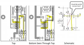
I took a look at the FirstWatt original boards to see if I could answer my question about the long run for the signal trace from C2 to R4, and I think I am seeing a difference between the schematic and the artwork in the manual. In the schematic the downstream side of C2 connects to R4 and Z2, but in the artwork the downstream side of C2 connects to R4, Z2, R6 & R8. Maybe I am seeing it wrong? Maybe it is not important?
Thoughts?
Thoughts?
Attachments
Last edited:
proper way is gate stopper being sole thing connected to gate
look at it as on Cerberus
Thanks Zen Mod, so in this case the artwork was right and the schematic should be reworked like the marked-up version in the previous post?
Just curious, why not use the existing F1 circuit board layout as a basis? The artwork has been published on page 8 of the F1 service manual:
Thanks for the suggestion Rodeodave, your comment made me look over the original design more closely and helped me answer my question about the long signal path trace in the layout I posted. I see that the original layout does not have long leads on the signal paths, so I reworked my layout to meet my design goals and reduce the signal path trace lengths. As a happy coincidence, the reworked layout is symmetric and won't need dedicated left and right hand boards
.I think the board is ready to release for fabrication and wanted to get any last minute input before I let it go.
Thanks!
Chas
Attachments
- Home
- Amplifiers
- Pass Labs
- Firstwatt F1J