F5T
More pics!
Allmost all mechanical work is done. My hands hurt and its late again. I thought i should share this with you guys.
That is an amp for a friend, his components. Due to lack of time, i offered him to build his F5T Version2 - Well that was fun.
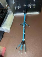
This first image is meant for a teaser, more to come, maybe in seperate thread.
More pics!
Oh, i forgot to tell you guys the best part, i havent payed a cent for this :
I need to change my address cus i aint gonna give this amp to his owner
Hehe, then you have to hurry, because the "owner" (it's me) knows where you live...
Can you explain a bit about the parts, and share some inside pics?
More?
this is during the last month of planing.
Squizing an elefant in an matchbox is quite a challenge sir.
Here you go:
this is during the last month of planing.
Squizing an elefant in an matchbox is quite a challenge sir.
Here you go:
Attachments

Hehe, then you have to hurry, because the "owner" (it's me) knows where you live...
Can you explain a bit about the parts, and share some inside pics?
OK the parts:
Fets:
IRF240/9240 from Vishay. These IRF can be replaced by better sounding stuff!
You have send me matched mosfets. I measured them and tossed em back in the bag. I chose 4 pairs of my own pair-matched IRF's. the pairs are matched very well under heat. The N AND the P Fets are close together also. I made screeshots from the analyser 4 you.
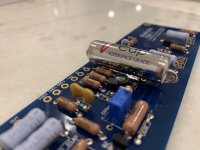
The 16 caps are rated for 22.000 / 63Volts / 125 degrees, suprising small and very heavy. These are Mundorf caps, and, boy, are they expensive.
I talked allready about the rectifiers; MUR3020 doublediodes - the real fun stuff.
Connecting cables:
Connecting the Speacon to the rectifiers 4mm² this Thomann Elefantcable.
Connecting from Rectifiers to Caps 4mm² Lithiumbattery superflexible silicon-cables.
Then connecting from Caps to the Powerboards each polarity 2,5mm² (you cant solder 4mm² to the boards this will be a mess)
Output to Speakerterminals:
Van den Hull 4mm² CS14 (This cables my favorite, i equiped my internal speakercabling with all Van den Hull - Amen!)
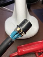
Ah, the Speakon connector from the Transformer-case ambylical cord to the amp is quite tricky. It reads 40amps - i doubt it. As soon as i do the powertest on this big test-heatsink i will see whats happening beyond 8 amps at 20 Hz. I am electrician - i break parts.
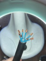
On the Transformerside nothing to write home about. This cable, Elefant 8x4mm² superflexible is the real deal for such a project. The audiophonics transformer likes to humm i little, you can't hear it case-closed in hearing position.
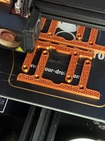
The PLA Parts WILL melt at 78 degree celscius, its the transitionpoint for this material, at 55-60 degree it is stable. I really regret not having the copper parts. Anyway your amp will blow you away. Any Class-D fanbois here? Hold my beer.
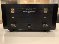
The chassis is a very nice work from french audiophonics shiped from china.
Closing this i like to say that all this plan was depending on the powertransmission over 1 cable 1meter long, from transformer to the amp. We are talking here 4 times 24Volts at serious amps
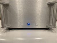
It took me weeks to find the cable and the connector. I mean, look at the capacitance - make them sing i though. And since you pay the bills i thought: Hey, Amps.Now this amp will have to burn in. The needle needs to be activated and illumination applied. Some Makeup-stuff
and voilà.
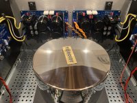
Ah..yes.. the problem with the space inside the amp-chassis.
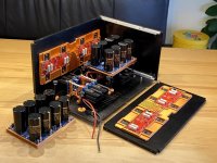
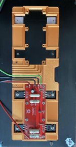
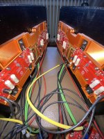
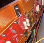
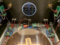
Since there are 16 caps, gold on black sleve, decision was made to place them in a row - V16 engine. Then the rectiviers had to go SOME-where, the choise was easy to make, after some 6 weeks and even more bottles of fine italian redwine i gave in to hide them just slighly under the capacitancebank. The monting-riggs for the diodes had to be constructed and printed, this turned out good. All Caps-banks and rectifier-riggs are mounted on rubberpads - we dont want vibrations on our chassis that make us no-sleep at night
Hard to beliefe that a pile of Non-wife-factor-parts soldered together make fine music.
My Pearl II
What a lovely phono stage!
Wow! What a Pearlamp. Nice work.
Wow! I finally get to listen to my "new" Medallion 2 cabinets with Lowther PM2A drivers, which I bought for my in progress Singing Bush VFET amplifier. Just finished listening to Andrea Bocelli sing Ava Maria in Italian, MAGICAL!
makes me wanna have.
My first Amp build. ACA stereo mode, home made enclosure made from old Douglas Fir/Oregon and a smps inside. Will monitor temp but seems to stabilise with heat sinks at 50deg with ambient about 15 deg. Using NAD 7225pe I repaired as preamp. Very happy with sound, its not a fatiging sound and seems to improve the longer its on ?
Cheers
Thats a nice tiny amp, my next project.
who can find the error?
THAT is a classic, who can tell?
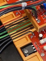
ok this was BEFOR 1st powerup.
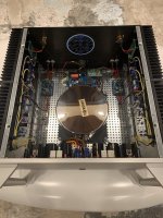
Ah..yes.. the problem with the space inside the amp-chassis.
Since there are 16 caps, gold on black sleve, decision was made to place them in a row - V16 engine. Then the rectiviers had to go SOME-where, the choise was easy to make, after some 6 weeks and even more bottles of fine italian redwine i gave in to hide them just slighly under the capacitancebank. The monting-riggs for the diodes had to be constructed and printed, this turned out good. All Caps-banks and rectifier-riggs are mounted on rubberpads - we dont want vibrations on our chassis that make us no-sleep at night
Hard to beliefe that a pile of Non-wife-factor-parts soldered together make fine music.
THAT is a classic, who can tell?
ok this was BEFOR 1st powerup.
Attachments

NPXP
@elven ears,
Amazing build and execution, I love the custom organization of your wirings and custom extrusions you placed on the heatsink for the F5 boards. Beautiful work.
My build is much more rudimentary but I do use an 800VA Toroidy with (4) 20V secondaries for ease of wiring and nearly a dual mono setup.
Best,
Anand.
Attachments
Last edited:
I didn't even saw that post .....
evidently selling in EU :
DIY Aluminium Case with Power Indicator and Heatsink 396x360x195mm - Audiophonics
evidently selling in EU :
DIY Aluminium Case with Power Indicator and Heatsink 396x360x195mm - Audiophonics
- Home
- Amplifiers
- Pass Labs
- Pictures of your diy Pass amplifier