If your cutting metal with a wood blade on a table saw , turn the blade around. You don’t want the teeth cutting into the metal, you want the blade to turn backwards for this. I have cut miles of metal roofing and steel with a Circular saw and table saw and found out very fast that you need to run the blade backwards. Or the teeth will start flying off the blade
My diy camp amp
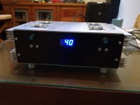
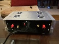
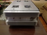
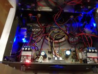
Hi guys . Just finished my diy camp amp
Hi guys . Just finished my diy camp amp
Attachments
Last edited:
Hi guys . Just finished my diy camp amp
Congratulations!! It's a great amplifier, you'll enjoy it!
")
Wonderful photos, the amplifier looks beautiful.
Last edited:
Hi guys . Just finished my diy camp amp
And what're the other bits and bobs I can see in there?
PS, looks great. I'm digging the ally and blue combo.
Cheers,
Aren.
Pass DIY Addict
Joined 2000
Paid Member
Just finished my diy camp amp
Awesome - does it fly with that many fans?
I'm imaging something like the world's first quad-copter-ClassA amp. In all seriousness, it looks like you have an amp that will stay nice and cool - a major accomplishment in this arena! These amps are addicting: I have one in my office that runs all day long every day and my kids also have one for a small bedroom stereo.
Hi guys . Just finished my diy camp amp
Love the industrial/lab type look of it
looks bad ***. Great job
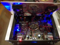
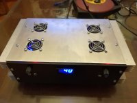
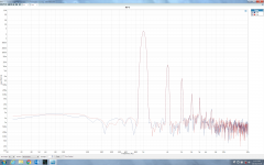
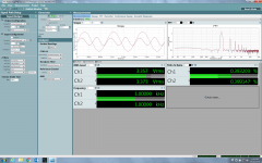
Here's the ACA I built from the boards I got from Burning Amp 2017, then I brought the finished amplifier back for Burning Amp 2018. I assembled it from a lot of surplus parts I had on hand, and I put the surplus 24V SMPS inside the chassis. I was worried about noise (SNR >90dB) and crosstalk (less than -70dB) but they both measured better than expected (see attached). I used an eBay chassis which is runs at about 60ºC when its 25ºC (I don't recommend this chassis). I used Dale RN55s for the most part and matched the resistors between channels, which helped achieve ~0.1dB channel matching. The unmatched IRFP240s were my leftovers from matching sets for an Aleph J, meaning they were far from being matched. I substituted the 10uF electrolytic coupling cap for a 1uF WIMA and it didn't seem to effect the LF. I used a 4700uF output cap because it was the only kind I had on hand that would fit the board.
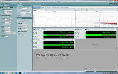
I ran a few measurements on an AP with a 1Vrms input, and using 8Ω loads. The amp is biased to 12V.
Thank you Mr. Pass for sharing yet another elegant amp design! And thank you to the diyAudio community for inspiring me to build it.
-Olen
I ran a few measurements on an AP with a 1Vrms input, and using 8Ω loads. The amp is biased to 12V.
Thank you Mr. Pass for sharing yet another elegant amp design! And thank you to the diyAudio community for inspiring me to build it.
-Olen
Attachments
-
 FFT 1Vrms input.png484.3 KB · Views: 188
 -
 1Vrms input ch2 input shorted.png531.6 KB · Views: 183
 -
 1Vrms input ch1 input shorted.png509.1 KB · Views: 194
 -
Signal to Noise Ratio.pdf191 KB · Views: 85
-
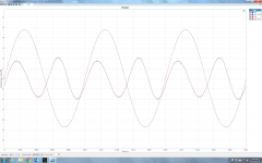 Residual +40dB Scope_2.png448.7 KB · Views: 1,198
 -
 Residual +40dB Scope.png522.2 KB · Views: 1,237
 -
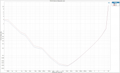 THD vs Power.png339.5 KB · Views: 1,374
 -
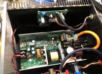 inside.jpg857 KB · Views: 1,396
 -
 outside.jpg521.3 KB · Views: 1,382
 -
ACA Gain.pdf262.1 KB · Views: 71
nothing exciting here since I used standard DIY Audio chassis and boards. My metalwork abilities have always been subpar so I prefer to use off-the shelf stuff or farm the work out to someone else.
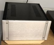
Here is my Aleph J without the front panel, first time listen:
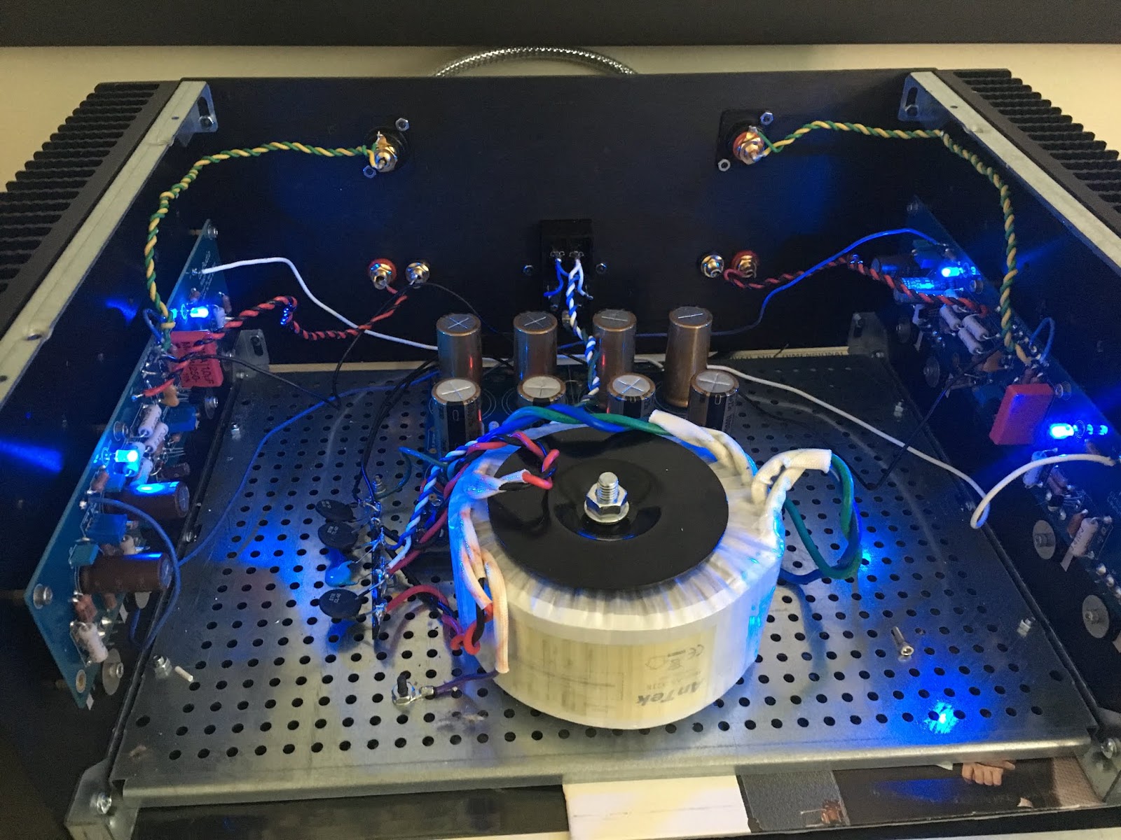
and buttoned up in low light with the LEDs glowing:
Here is my Aleph J without the front panel, first time listen:
and buttoned up in low light with the LEDs glowing:
Hi guys . Just finished my diy camp amp
Congratulations and I like the fan idea. It's a good deviation away from having to use the same standard heat sinks.
Nice work.
That's my preferred way of showing on/off - the blue glow coming up through the vent holes.
Looks cool, and probably a bad idea to keep something on top of a Class A amplifier that can block the bluish glow (and the ventilation).
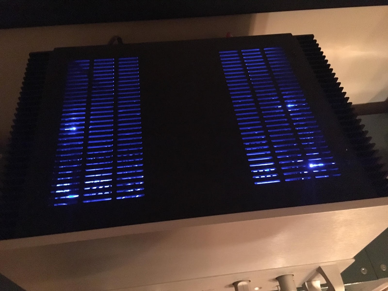
Very nice. What is underneath the power amp in the second image? Is it a DIY preamp with handles?
I wish it was a DIY creation but it's a Classe Five preamplifier - pretty rare - 1990s version of their old 1980s DR-5. It has all the bells and whistles I need, including a MC head amp, a set of XLR in and out, along with a very heavy remote control.
Hello, here is my newly completed F6 amp:

I just wanted to come in and thank everyone who has posted in this thread, the F6 threads, and others. There was a lot of knowledge and info from this site that helped me construct this successfully.
The whole build gallery is here First Watt F6 - Album on Imgur if anyone is interested.
I just wanted to come in and thank everyone who has posted in this thread, the F6 threads, and others. There was a lot of knowledge and info from this site that helped me construct this successfully.
The whole build gallery is here First Watt F6 - Album on Imgur if anyone is interested.
- Home
- Amplifiers
- Pass Labs
- Pictures of your diy Pass amplifier