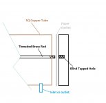
I've always admired the method posted in some thread here of just soldering a strip of copper, say 1/8" thick 1.5" wide, along it's edge to some 1/2" copper pipe to create the active device waterblock. You then bolt the output devices through the copper strip and connect the tubing to the copper pipe.
A square copper tube with water flowing through would be really easy to mount the active devices to but need to have the ends sealed and any bolts through the wall holding devices also so is probably more difficult in the end. .
A square copper tube with water flowing through would be really easy to mount the active devices to but need to have the ends sealed and any bolts through the wall holding devices also so is probably more difficult in the end. .
Last edited:
The same technique I used for the cooler block can work with the square tube. Just make sure it isn't ferrous to prevent rust. Of course ends can also be soldered as can the inlet and outlet.
The only negative with the tube is heat transfer from the power transistors sequentially through the tube. A bi-directional flow might solve the problem. I'm working on such a drilled block as X has suggested.
Here is a link to the preliminary results from yesterday. I'm working on a mod of a PC PS with rheostats on full 12 VDC to run through a bunch of air vs. fluid flow scenarios.
Attachments
Last edited:
I've always admired the method posted in some thread here of just soldering a strip of copper, say 1/8" thick 1.5" wide, along it's edge to some 1/2" copper pipe to create the active device waterblock. You then bolt the output devices through the copper strip and connect the tubing to the copper pipe.
A square copper tube with water flowing through would be really easy to mount the active devices to but need to have the ends sealed and any bolts through the wall holding devices also so is probably more difficult in the end. .
Nice stuff, nice reading. I hope I can go to burning amp festival, that would be like six flags for me.
DIY Copper Heat Pipes/Thermosyphons for heat removal
The amount of heat that water can remove is huge and the thermal conductivity of the copper will help to even out the lateral variation in temperature so much that you don't have to worry about this. Especially if you have any appreciable flow through the copper pipe.
What Variac proposed with a plate of copper soldered to a 1/2 in copper pipe is exactly what I was going to propose but with a twist: set the pipe vertically and make it long enough so that the top acts as a condenser and use it as a sealed system in thermosyphon (gravitationally assisted heatpipe). It is easy to make your own sealed heat pipe - see for example DIY Heat pipe The comments left by @foreverdisturbed on the Instructables website are very useful (trick about using dulled wire cutters for a pinch off cold welder).
You may want to attach so fins to the top section for it to radiate heat off by convection, or just use a longer pipe.
Sometimes the secondary heat removal problem can be almost as interesting as the primary problem of building a class A amp.
Just a side note: for those not familiar with why even bother with a heat pipe? They are not only passive, but if properly designed, offer the greatest thermal heat transfer flux per cross sectional area - greater than pure gold or solid diamond, and for a liquid sodium heat pipe, is only exceeded by the heat flux at the surface of the sun! The movement of hot evaporated molecules carrying heat of vaporization at sonic speeds carries a lot of heat.
The only negative with the tube is heat transfer from the power transistors sequentially through the tube. A bi-directional flow might solve the problem. I'm working on such a drilled block as X has suggested.
The amount of heat that water can remove is huge and the thermal conductivity of the copper will help to even out the lateral variation in temperature so much that you don't have to worry about this. Especially if you have any appreciable flow through the copper pipe.
What Variac proposed with a plate of copper soldered to a 1/2 in copper pipe is exactly what I was going to propose but with a twist: set the pipe vertically and make it long enough so that the top acts as a condenser and use it as a sealed system in thermosyphon (gravitationally assisted heatpipe). It is easy to make your own sealed heat pipe - see for example DIY Heat pipe The comments left by @foreverdisturbed on the Instructables website are very useful (trick about using dulled wire cutters for a pinch off cold welder).
Code:
Hello, I worked for Thermacore Inc. For 18 years making heat pipes and thermosiphones. Thermosiphones work gravity aided and can be made with water, methanol or acetone as a working fluid and are usually used for high power/heat applications. A heat pipe is not gravity aided and is usually always uses water as a working fluid and is for low power/heat applications. Thermosiphons can usually be made by a novice but, still needs to be done right to work properly for instance do not use solder use braze and you should braze with hydrogen and oygen so you don't need to use flux. Flux would be a contaminate and will off gas causing you thermosiphon to eventualy fail. Solder will cause the same problem. You need to use OFHC (oxygen free) Copper tube and caps. Your pipe needs to be very clean of any oils or grime inside this will also contaminate and offgas. When you process you thermosiphon it needs to be under a vacumme while processing and while sealing it. To do this add a small filltube to the top end of your pipe and then heat the bottom until you start to see fluid comming out and the top of the pipe is as hot as the bottom then you can use a modified wire cutter with the sharp edges filed rounded. Use the cutter to pinch the fill tube closed this should give you a leak tight seal. This is called a cold weld. After it is sealed and the pipe is still hot you can put a piece of glass or mirror above the fill tube to see if it leaks. If it leakes but is still hot you can just keep pinching it closed till you get it sealed. There is a special tool for this but, it is very expensive. The smaller diameter the fill tube is the easyer it will be to seal. 1/16" fill tube would be best but, no larger than 1/8" also heat up the fill tube red hot prior to processing that way the fill tube will be softer and easyer to seal. Hope this helps you or ntone else trying to make a thermosiphon. If you have any questions you can e-mail me at disturbeddesign@yahoo.comYou may want to attach so fins to the top section for it to radiate heat off by convection, or just use a longer pipe.
Sometimes the secondary heat removal problem can be almost as interesting as the primary problem of building a class A amp.
Just a side note: for those not familiar with why even bother with a heat pipe? They are not only passive, but if properly designed, offer the greatest thermal heat transfer flux per cross sectional area - greater than pure gold or solid diamond, and for a liquid sodium heat pipe, is only exceeded by the heat flux at the surface of the sun! The movement of hot evaporated molecules carrying heat of vaporization at sonic speeds carries a lot of heat.
Last edited:
Well, I got one foot in the water (pun intended) as I ordered some 1-1/2" x 1-1/2 aulminum square tube this morning. Copper/Brass was just too expensive for this experimental phase. I have been planning a vertical/post/tower for the next version and I'll surely investigate the heat pipe links thoroughly. Thanks
Getting closer to the target as I now own all the boards to build a Burning Amp #1 or #3. I chose single ended because it appears that it runs hotter than the complementary. In any case it will get me to higher temps to contend with.
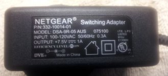
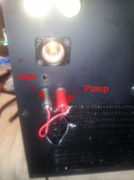
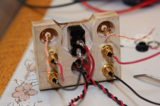
I had one tiny leak that prompted me to complete rework the location of some joints (Yesterday I couldn't spell engineer and now I are one ) so with my new handy-dandy 12 and 5 VDC PS, I'm ready to get back to the air/liquid flow ratio tests. Should have some info tomorrow.
Getting closer to the target as I now own all the boards to build a Burning Amp #1 or #3. I chose single ended because it appears that it runs hotter than the complementary. In any case it will get me to higher temps to contend with.
I had one tiny leak that prompted me to complete rework the location of some joints (Yesterday I couldn't spell engineer and now I are one
) so with my new handy-dandy 12 and 5 VDC PS, I'm ready to get back to the air/liquid flow ratio tests. Should have some info tomorrow.Attachments
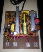
Can't tell you - I tossed the case many moons ago. I'm guessing it's a standard PC 200 from the only number (12 digits) on the PCB. I'm sure it is major overkill as both pump and fan are working great with just a spare wall wart. It's mostly for convince and future bench work. Just have to add the rheostats.
Attachments
Just to dilute your smart thermodynamics arguments, let me post my "F5 invasion" photo. If you don't mind

What's the black amp in the back ground ...?
Pass DIY Addict
Joined 2000
Paid Member
My Daughter's ACA
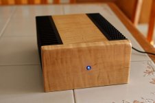
Last weekend, my daughter and I built an Amp Camp Amp for her birthday. The full story is here.
In this thread, I wanted to add more pictures of the amp itself with the hope that it might give someone else some ideas. The chassis is made from a 1x4" piece of hard maple that I picked up at the local hardware store. It was sanded and finished with a Fruitwood stain (very light color) and topped off with two coats of Polyurethane.
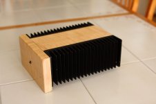
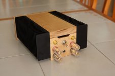
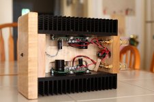
The sinks are the 2U sinks from the DIYAudio store. I had to route out the underside of the top plate making it thinner in order to make room for the PCB when mounted on the sink. The front panel is a double thickness of wood, with the inner piece cut smaller. This provides a way to drive screws through the heat sink directly into the wood on the backside of the front panel, keeping things a little cleaner looking.
I also cut a small vent in the rear panel to allow some warm air to escape. The front and rear panels extend down beyond the bottom of sink by about 1/2" to allow some air up into the chassis. Not shown in the photo are the little rubber "feet" that I added to the bottom. I used the left over self-adhesive gasket material from the speakers to keep the amp from scratching up the surface of her dresser.
The completed amp gets mildly warm. While I haven't measured it, I'd guess it barely sees 10-15 above body temp.
When powered on, the amp is DEAD SILENT. No hiss, no hum, just silence until you press Play.
Last weekend, my daughter and I built an Amp Camp Amp for her birthday. The full story is here.
In this thread, I wanted to add more pictures of the amp itself with the hope that it might give someone else some ideas. The chassis is made from a 1x4" piece of hard maple that I picked up at the local hardware store. It was sanded and finished with a Fruitwood stain (very light color) and topped off with two coats of Polyurethane.
The sinks are the 2U sinks from the DIYAudio store. I had to route out the underside of the top plate making it thinner in order to make room for the PCB when mounted on the sink. The front panel is a double thickness of wood, with the inner piece cut smaller. This provides a way to drive screws through the heat sink directly into the wood on the backside of the front panel, keeping things a little cleaner looking.
I also cut a small vent in the rear panel to allow some warm air to escape. The front and rear panels extend down beyond the bottom of sink by about 1/2" to allow some air up into the chassis. Not shown in the photo are the little rubber "feet" that I added to the bottom. I used the left over self-adhesive gasket material from the speakers to keep the amp from scratching up the surface of her dresser.
The completed amp gets mildly warm. While I haven't measured it, I'd guess it barely sees 10-15 above body temp.
When powered on, the amp is DEAD SILENT. No hiss, no hum, just silence until you press Play.
Attachments
Last edited:
Pass DIY Addict
Joined 2000
Paid Member
Hi Vince,
I was just thinking since the chassis was wood rather than metal, it might be better to allow some way for air to move inside. I don't really see this as a major concern as all of the components inside are rather well behaved. The big power resistors seem to run at about body temp and the sinks are just a bit warmer than that.
I think it was more of a "because I could" design feature...
Nice looking amp. If concerned about the heat, seems like one could easily route a 1/4" to 1/2" wide slot top center and add some complementary holes or slots on the bottom. Looks like the bottom sits up enought to make that workable.
Jumped to the top of my case list. I have the ACA kit and plenty of aluminum, but I also have a couple of smallish pieces of Paduak that haven't been assigned to a project.
Jumped to the top of my case list. I have the ACA kit and plenty of aluminum, but I also have a couple of smallish pieces of Paduak that haven't been assigned to a project.
Pass DIY Addict
Joined 2000
Paid Member
When powered on, the amp is DEAD SILENT. No hiss, no hum, just silence until you press Play.
yup, one of the perks of 40khz smps operation
btw, very nice enclosure indeed !
Paduak.....paduak....!!
If you like paduak, check out post #728 in this thread. I love using this wood on my amps!
Oooo... I like Paduak! I was thinking of getting my hands on some of this for my next speaker project.
If you like paduak, check out post #728 in this thread. I love using this wood on my amps!
- Home
- Amplifiers
- Pass Labs
- Pictures of your diy Pass amplifier