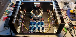
Those are 14ga I think. I'd like to reuse the power supply section for something else, so when I do that I'll take care of those wires then.What wire is coming out of the transformer to the diode bridges, it should be labeled on the wire, looks like an Antek. That would give you an idea of what size wire the rest needs to be.
Very nice build, congrats.Good evening to all the friends of the forum, it is my first post and also thanks to all of you who have returned my passion for self-construction of audio components.
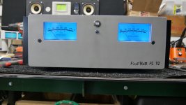
After several months of finding both the material and the time I was able to finish the electronic and good mechanical part of my amplifier.
It is a particular project because there are 2 class A amplifiers in a single self-built chassy, a 5 + 5w powered by a 24v switching power supply and a pair of 60 + 60w aleph 5 clones powered by a linear power supply with a toroidal built specifically for have the two channels completely separate.
The two amplifiers are exchanged both in input and output with a series of relays that also act as protection for the speakers, in order to manage energy consumption based on use and listening volume.
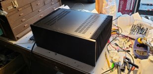
I still have to finish the chassy with wooden sides and an aluminum bottom.
Sorry for my English, I use Google Translate, I'm an Italian & Tuscuany D.O.C. !!
View attachment 1014774 View attachment 1014775 View attachment 1014776 View attachment 1014777 View attachment 1014778 View attachment 1014779 View attachment 1014780 View attachment 1014781 View attachment 1014782 View attachment 1014783 View attachment 1014784 View attachment 1014785
Wouldn't it be better to twist all the AC wires?
Good evening, the speaker wiring and power supply are temporary, today I received the rigid cable and connectors to finish the wiring waiting for the wooden parts to finish the assembly, this week with the temporary wiring I checked that there are no problems with stability, for now I'm happy with the sound and the working temperature. As soon as the project goes on I will have more photos.Very nice build, congrats.
Wouldn't it be better to twist all the AC wires?
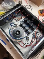
Just change the cap bank with the transformer to eliminate the ground loop.Standard-issue F5 kit and 4U chassis from the DIYAudio store. Biased at 0.59V, 9mV DC offset. Sounds great except for a slight hum. Still have to play around with grounding scheme.
Sorry, not following.Just change the cap bank with the transformer to eliminate the ground loop.
Swap position between the transformer and PSU caps. You can just rotate 180º the bottom panel or move the back panel to the front.
The idea is to keep the toroid as far as possible from the input signal to reduce risk of electromagnetic induction causing some hum.
If this does not solve your problem, it is nevertheless a good practice to follow.")
The idea is to keep the toroid as far as possible from the input signal to reduce risk of electromagnetic induction causing some hum.
If this does not solve your problem, it is nevertheless a good practice to follow.
My philosophy was to keep the wires carrying line voltage as short as possible, hence the transformer in the back, under the power inlet. I didn't want 120VAC wires running to the front of the amp if I didn't have to have them. I will try your suggestion and see if it helps. I've had this issue in the past with other amps and successfully eliminated it by using a full dual-mono power supply setup FWIW.
My philosophy was to keep the wires carrying line voltage as short as possible, hence the transformer in the back, under the power inlet. I didn't want 120VAC wires running to the front of the amp if I didn't have to have them. I will try your suggestion and see if it helps. I've had this issue in the past with other amps and successfully eliminated it by using a full dual-mono power supply setup FWIW.
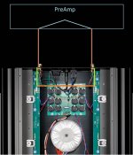
Here how the original FW looks like. I guess it is always a matter of trade-offs. Let us know if (or what) works for fixing your issue.
Sorry, It was not correct.Just change the cap bank with the transformer to eliminate the ground loop.
You can't eliminate the ground loop, but you can easily remove the transformer from the loop.
Attachments
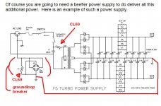
Look at how Nelson recommends connecting mains ground to the chassis and power supply ground. This will eliminate hum and keep you safe.Sounds great except for a slight hum.
Attachments
I too have a slight hum after following the F5 PSU schematic, so I'll also give the F5T ground scheme a crack too
Its only a slight hum... actually probably more on the buzz side than hum and can only hear it with my ear against the bass driver, nothing at all from the tweater
Its only a slight hum... actually probably more on the buzz side than hum and can only hear it with my ear against the bass driver, nothing at all from the tweater
Last edited:
- Home
- Amplifiers
- Pass Labs
- Pictures of your diy Pass amplifier