Here are some photos of the latest attempt to combine computer liquid cooling and power amps. This one is performing far beyond expectations. I jokingly have dubbed it the “flush”, as it based on the same principle as the drain tube in the water tank off a ...umm water closet. Great credit goes to XRK971 here on the forum – he informed me that water has an enormous heat adsorption capacity – far beyond any metal. Many thanks Mr. X.
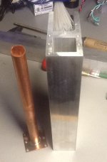
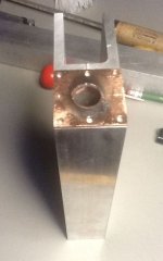
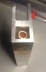
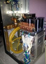
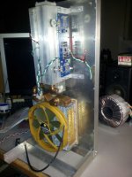
I selected a 1” X 1” X ¼ aluminum tube because of it's natural heat absorption and it also allowed comfortable margins to use threaded 6-32 bolts on the ends. Every attempt to use blind holes where possible was made to avoid leaks. The internal drain tube is 5/8” standard copper tube and extends to within a 1/4” of the top of the cooler. That insures all air will be pushed out of the cooler body and eliminates the need for a separate external return tube or hose. Drilled laminated Plexiglas also serves to minimize many leak prone hose elements. All of those mating surfaces have automotive paper gaskets that swell when a liquid is present, and allows diss-assembly without scraping off a lot of dried goo.
I selected a 1” X 1” X ¼ aluminum tube because of it's natural heat absorption and it also allowed comfortable margins to use threaded 6-32 bolts on the ends. Every attempt to use blind holes where possible was made to avoid leaks. The internal drain tube is 5/8” standard copper tube and extends to within a 1/4” of the top of the cooler. That insures all air will be pushed out of the cooler body and eliminates the need for a separate external return tube or hose. Drilled laminated Plexiglas also serves to minimize many leak prone hose elements. All of those mating surfaces have automotive paper gaskets that swell when a liquid is present, and allows diss-assembly without scraping off a lot of dried goo.
Attachments
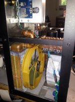
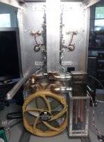
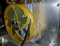
The radiator is actually a heater core from a Ford Mustang purchased years ago from the former computer cooling enterprise – Danger Dan. They are available at most auto supply stores and of course, your local junk yard. This one was ~ $25. The fan is a Thermalright TR TY – 150. It is capable of rotating between 500 and 1100 RPM.
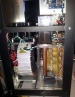
The water circulation system consists of a tiny DC submersible pump, again to eliminate tubes and hoses even more. In and out flow is accomplished using 3/8 copper tube. The extended return terminates at a point below the functional water level and defeats the natural tendency of water to seek it's lowest level. As long as the loop is sealed the reservoir can be located at any location.
The water circulation system consists of a tiny DC submersible pump, again to eliminate tubes and hoses even more. In and out flow is accomplished using 3/8 copper tube. The extended return terminates at a point below the functional water level and defeats the natural tendency of water to seek it's lowest level. As long as the loop is sealed the reservoir can be located at any location.
Attachments
Last edited:
So how efficient is it? I almost fell off my chair in disbelief at the first test Friday evening. With the F5 operating for forty minutes, ambient was 26 C, cooler was 27 C and the bolt on the power transistor was 27 C.
WOOOPPPEEE !!
Those temps stayed consistent for over an hour. A quick message to 6L6 confirmed it was actually running far below optimum temperatures for the F5. In all honesty, I had intended this radiator for a Burning Amp project in the future, but as the previous version (#4), using a double thick radiator with two 80 mm fans only produced .045 c/w (less than air systems), I went for “Mustang Sally” as Mr. X calls it.")
The first test used an 8.5 VDC wall wart for the fan and a 5 VDC for the pump. No sound could be heard at 2 feet. I oriented the fan to draw air in to use the case as a noise dampener – if necessary. Using the 5 V PS for both fan and pump all but eliminates any concern for rotation and/or vibration noise. I'll include a recording in the full build post to come later on the other thread.
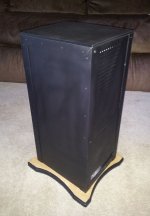
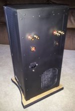
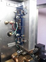
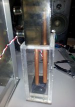
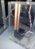
I started a presentation chassis a few days ago that strives to keep the entire system as compact as possible. It is a work in progress and I skipped several elements such as the thermistor system, a power switch/LEDs and both the radiator and the reservoir still need drains. It's very utilitarian now and needs a lot more wood trim to cover screws and rivets and other cosmetics. The top is actually phoney, but I'm tired.
All in all, I'm quite happy with the results. The next application appears to be the BA project packed in a 8” X 10” X 12” chassis with maybe four output boards . I'll probably bump this F5 back down to a standard 120 mm system that works well with the Honey Badger clone.
Now that's a "COOL" F5 amp,
WOOOPPPEEE !!
Those temps stayed consistent for over an hour. A quick message to 6L6 confirmed it was actually running far below optimum temperatures for the F5. In all honesty, I had intended this radiator for a Burning Amp project in the future, but as the previous version (#4), using a double thick radiator with two 80 mm fans only produced .045 c/w (less than air systems), I went for “Mustang Sally” as Mr. X calls it.
The first test used an 8.5 VDC wall wart for the fan and a 5 VDC for the pump. No sound could be heard at 2 feet. I oriented the fan to draw air in to use the case as a noise dampener – if necessary. Using the 5 V PS for both fan and pump all but eliminates any concern for rotation and/or vibration noise. I'll include a recording in the full build post to come later on the other thread.
I started a presentation chassis a few days ago that strives to keep the entire system as compact as possible. It is a work in progress and I skipped several elements such as the thermistor system, a power switch/LEDs and both the radiator and the reservoir still need drains. It's very utilitarian now and needs a lot more wood trim to cover screws and rivets and other cosmetics. The top is actually phoney, but I'm tired.
All in all, I'm quite happy with the results. The next application appears to be the BA project packed in a 8” X 10” X 12” chassis with maybe four output boards
. I'll probably bump this F5 back down to a standard 120 mm system that works well with the Honey Badger clone.Now that's a "COOL" F5 amp,
Last edited:
..... water has an enormous heat adsorption capacity – far beyond any metal.
water removes heat very fast
but only if you continue to remove the accumulated heat from the water
or else the cooling process ends
oh lord, I had not yet seen the last page
coool

You should put a few drops of BLEACH in the water to kill some bacterias or the water will start smelling bad with time.
Maybe do a salt water version with a chlorine generator.
The radiator is actually a heater core from a Ford Mustang purchased years ago from the former computer cooling enterprise – Danger Dan. They are available at most auto supply stores and of course, your local junk yard. This one was ~ $25. The fan is a Thermalright TR TY – 150. It is capable of rotating between 500 and 1100 RPM.
The water circulation system consists of a tiny DC submersible pump, again to eliminate tubes and hoses even more. In and out flow is accomplished using 3/8 copper tube. The extended return terminates at a point below the functional water level and defeats the natural tendency of water to seek it's lowest level. As long as the loop is sealed the reservoir can be located at any location.
Bravo
while you are there what voltage / bias you running
Any chance you can take it up (way up) and give us listening impressions
Can you measure the temperature on the drain leg of the mosfet as it came out of body that is the nearest point to the junction where all Papa magic happens
PS whit 3 different metals already I would certainly avoid putting any kind of stuff in the water corrosion set in pretty quick
Ever tried muriatic acid to etch PCB?
Last edited:
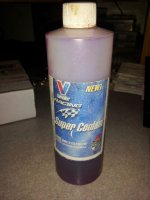
I use this. It handles corrosion, bacteria and boosts the heat transfer.
6L6 suggested adjusting the bias also, but it appeared I was trading one problem - excessively low operation temps - for another - a lot of fiddling that might not provide any appreciable increase in sound quality. I'll do some tests and report the results. This system is really too much for the F5, but the format using the above mentioned 120 mm system will probably be the right fit.
6L6 suggested adjusting the bias also, but it appeared I was trading one problem - excessively low operation temps - for another - a lot of fiddling that might not provide any appreciable increase in sound quality. I'll do some tests and report the results. This system is really too much for the F5, but the format using the above mentioned 120 mm system will probably be the right fit.
Attachments
Last edited:
WOW! That is so much more elegant than the beer cans, old frying pans, scrap metal, fridge shelves, etc... that I use for heatsinks.
Thanks Daniel, Now you see why I've been delinquent on the TDA project
 . I'll be back there ASAP.
Pass DIY Addict
Joined 2000
Paid Member
Respect Bob ! like your style !
For those interested, there's a whole universe of water cooling solutions out there ....
For those interested, there's a whole universe of water cooling solutions out there ....
I don't believe this................ A quick message to 6L6 confirmed it was actually running far below optimum temperatures for the F5. .........
I wonder what proportions of believers have seen evidence to support the contention?
From Pass DIY - Burning Amplifier #1
"Heat sinks should stabilize at a temperature at which you can put your hand on the heat sinks for about 5 seconds. This is between 50 and 55 deg C, and is the ideal figure. As mentioned before, you should consider better ventilation or less bias if the heat is much greater."
"Heat sinks should stabilize at a temperature at which you can put your hand on the heat sinks for about 5 seconds. This is between 50 and 55 deg C, and is the ideal figure. As mentioned before, you should consider better ventilation or less bias if the heat is much greater."
- Home
- Amplifiers
- Pass Labs
- Pictures of your diy Pass amplifier