It’s been suggested that a tweeter isn’t needed.
I thought about adding 045BE , but after many conversations and living with 2435 in a 2-way I must admit I’m a little torn . I’ll add it if needed . I want to see how close I can get this combination to my TAD 2404 .
I
Have another pair of H9800 if you’re interested ?
Richard
I thought about adding 045BE , but after many conversations and living with 2435 in a 2-way I must admit I’m a little torn . I’ll add it if needed . I want to see how close I can get this combination to my TAD 2404 .
I
Have another pair of H9800 if you’re interested ?
Richard
Got a driver voltage curve for it?
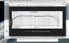
See post#2 for the SPL and impedance plot.
Truextent Diaphragms in JBL four-inch compression drivers
I have the 2446H with Yuichi A290 horn (blue plot).
The low end is open-baffle AE Dipole 15.
Plan to cross at 600Hz region (recommended for the A290 horn)
Last edited:
Post 34
Truextent diaphragms measurements - Page 3
Rich
send me sope picture and price per PM
how low can they go?
Truextent diaphragms measurements - Page 3
Rich
The LXmini crossover itself would have the wrong settings, but the
board design should pretty much accommodate the curves I saw
assuming that 12 dB/octave is a suitable slope for you. It looks like
you might want a gentle depression in the upper mid, which is
allowed for in the artwork.
If you knew what curve you wanted specifically, then fixed resistor/cap
values could be used, and the existing LXmini artwork could serve.
However, I suspect that an adjustable version is what is going to be
needed, as I doubt we know the exact curves.
I have such a version in the works, where there are pots on the board,
allowing a 3:1 adjustment of frequencies for the crossovers and some
smaller adjustment for a low Q notch. If I stick it on my vast to-do list
it could be ready in a month or so.
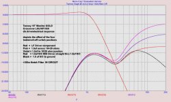
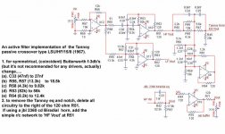
I want to try the DIY B4 in a biamp setup for a pair of Tannoy Monitor Golds. The circuit for the horn in the passive crossover incorporates a notch filter at ~ 3kHz and a slope correction at higher frequencies. I was thinking I could just retain that part of the passive crossover and use the B4 for the high and low pass. Does that make sense, or is it likely to be better to incorporate all of the corrections in the active crossover (which sounds pretty complex...).
I am attaching some curves representing the passive crossover corrections from John Riddley (tannoy). The violet line represents the correction without roll off in the tannoy crossover. The HPD probably uses a similar circuit - same tweeter. I have seen schematics for active crossovers, but the correction circuit looked very complex.
Attachments
Last edited:
I have the Tannoy 15" HPD coaxial Gold from early 60's. Is that similar
to yours? Crossover curve looks a bit different.
I'll be keen to see that schematic, though my electronics skills are pretty rudimentary.
The HPD succeeded the Monitor Gold some time in the 70s. The tweeter / horn remained little changed across many generations of the vintage Tannoys, and the HPDs and Golds have pretty much identical circuits for the tweeters in their crossovers. The earlier Reds didn't have a notch filter, so I guess they had a nice peak in their response.
in my experience , most complete (passive) xover/s for Pepperpot equipped DCs (doesn't matter what type of magnet) are Type 1009 and Type 1011 , used for K3808 and K3838 , practically SRM boxes
there is , if nothing else, practical survey of everything needed for Pepperpot Beastie to work
btw. time delay circuit thingie is waste of time
find downloadable pdf here : Dropbox - support.tannoy Tech_Manual_K3808_K3838.pdf
there is , if nothing else, practical survey of everything needed for Pepperpot Beastie to work
btw. time delay circuit thingie is waste of time
find downloadable pdf here : Dropbox - support.tannoy Tech_Manual_K3808_K3838.pdf
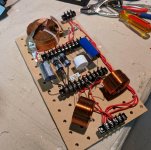
I had a look. The high pass, notch filter, and equalization look like the same design as the Monitor Gold. The results you get with a passive crossover seem to vary a lot depending on the type of caps you use in the tweeter circuit. I wound up building a crossover that allowed you to swap out the capacitors easily.
Attachments
that's easy - just use good ones")
It's not just how "good" they are - there seems to be synergy with certain types of caps. I just downgraded from Jantzen Superior Z caps to a mix of Clarity ESA and Mundorf EVO oil caps, and it sounds better.
However, I suspect that an adjustable version is what is going to be
needed, as I doubt we know the exact curves.
I have such a version in the works, where there are pots on the board,
allowing a 3:1 adjustment of frequencies for the crossovers and some
smaller adjustment for a low Q notch. If I stick it on my vast to-do list
it could be ready in a month or so.
Adjustable will be good. But if the fixed component can be easily calculated, we can try out various settings.
- Status
- This old topic is closed. If you want to reopen this topic, contact a moderator using the "Report Post" button.
- Home
- Amplifiers
- Pass Labs
- Pass Labs B4 crossover questions