The normal inrush current limiters consist of one or more NTC resistor in series to the primary winding of transformer like this
MS35 OR550 Inrush Current Limiter Data Sheet
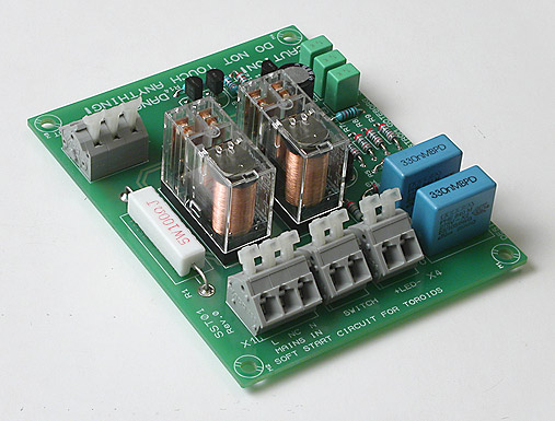
or a high power resistor, which is shortet by a relay after few seconds - like the circuit describted here:
Soft-Start Circuit For Power Amps
The first solution I can accept, if I choice the biggest NTC that have 35mm diameter
The second solution I hate, because the resistor always limit the current, if the relais contact don't longer work (transition resistance through wear and tear)
But this solution could be the royal way:
An inrush current limiting based on a controlled premagnetizing of the toroidal core. Premagnetising of the core with unipolar voltage impulses until the remanence reaches the maximum. Then full switch on, and then shorting through the bypass relay to connecting the primary winding directly to the mains connection.
Why use this approach no commercial power amplifier brands?
This technology could be a very fine solution for the large transformers in the Pass Labs power amplifiers. Additional there is the possibility now to use extremly low loss transformers.
read more about this
Transformer softstart Introduction : EMEKO, Michael Konstanzer
and this
System and method for limiting AC inrush current - Patent 7511975
MS35 OR550 Inrush Current Limiter Data Sheet
or a high power resistor, which is shortet by a relay after few seconds - like the circuit describted here:
Soft-Start Circuit For Power Amps
The first solution I can accept, if I choice the biggest NTC that have 35mm diameter
The second solution I hate, because the resistor always limit the current, if the relais contact don't longer work (transition resistance through wear and tear)
But this solution could be the royal way:
An inrush current limiting based on a controlled premagnetizing of the toroidal core. Premagnetising of the core with unipolar voltage impulses until the remanence reaches the maximum. Then full switch on, and then shorting through the bypass relay to connecting the primary winding directly to the mains connection.
Why use this approach no commercial power amplifier brands?
This technology could be a very fine solution for the large transformers in the Pass Labs power amplifiers. Additional there is the possibility now to use extremly low loss transformers.
read more about this
Transformer softstart Introduction : EMEKO, Michael Konstanzer
and this
System and method for limiting AC inrush current - Patent 7511975
Last edited:
I can only speak for myself. My solution will work more than 20 years for a 600 VA transformer, infact my have worked since 1988 = 32 years. It's pretty reliable. The amp is used every day since I have it for the TV sound. More info hereThe second solution I hate, because the resistor always limit the current, if the relais contact don't longer work (transition resistance through wear and tear)
...have worked since 1988 = 32 years.
22 not 32, but still good!

R1 = 100 ohms but only 5 watts. What happens, if relay contact don't short it?
Independend of this - 600VA don't say about the DC resistance of the primary winding coil
In the attachement you will find the schematic of Emeko's formerly softstart unit (from me created)
Independend of this - 600VA don't say about the DC resistance of the primary winding coil
In the attachement you will find the schematic of Emeko's formerly softstart unit (from me created)
Attachments
Honestly I am amazed at what some people attempt to patent.
The standard inrush protection for high power transmitters was a variation of a series resistor with an RC time constant relay contact to bypass the series resistor and or step from delta to star configuration, what ever it takes. AKA the solution presented by peranders.
The standard inrush protection for high power transmitters was a variation of a series resistor with an RC time constant relay contact to bypass the series resistor and or step from delta to star configuration, what ever it takes. AKA the solution presented by peranders.
Honestly I am amazed at what some people attempt to patent.
The standard inrush protection for high power transmitters was a variation of a series resistor with an RC time constant relay contact to bypass the series resistor and or step from delta to star configuration, what ever it takes. AKA the solution presented by peranders.
The mention of the URL
System and method for limiting AC inrush current - Patent 7511975
was a mistake from me - this patent have to do nothing with this subject here, because there are treated a 3-phase main connection and here only a 1-phase main connection !!
peranders said:I can only speak for myself. My solution will work more than 20 years for a 600 VA transformer, infact my have worked since 1988 = 32 years. It's pretty reliable. The amp is used every day since I have it for the TV sound.
By post #5, I had forgotten to mention this URLs:
http://www.emeko.de/uploads/media/01-comparison-esb-ter-e_fzesb_tsr-e.pdf
http://www.emeko.de/uploads/media/02-ERT-GR.pdf
Transformer soft start "State of the Art" - best soft start method until this time
http://www.emeko.de/uploads/media/01-Vergl-TSR-TrafoSTART.png
Last edited:
It will burn but the likelihood is rather low. If you still are afraid of that you can take measures.R1 = 100 ohms but only 5 watts. What happens, if relay contact don't short it?
Yes it does actually if you are in the business. A normal transformer has a range of primary winding resistance.Independend of this - 600VA don't say about the DC resistance of the primary winding coil
It will burn but the likelihood is rather low. If you still are afraid of that you can take measures.
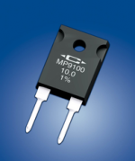
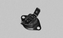
If you substitute your 100 Ohm 5 Watt resistor through a TO220/247 version from Caddock (together with a heatsink and a overheat switch), then I get more familiar with this topology
An additional step to enhance the reliability could be the mechanical relais contacts through a solid state switch solution. But therefore I need triacs or alternistors appropriate to switch on/off large toroidal transformers. Who knows types that match this requirement?
Somewhere here on this forum even MOSFETs have been recommend instead relais contacts - if I recall right.
Here some URLs in this case
http://www.caddock.com/Online_catalog/Mrktg_Lit/MP9000_Series.pdf
...::: ams TECHNOLOGIES DE - MP9100 Power Film ResistorsResistance 0,050 Ohm to 100 Ohm, 100 Watts, TO-247 Style :::...
Attachments
Last edited:
What values of NTC's? How long?
I use the NTC method, lately a series pair of CL-60s (10 ohm, 5A) bypassed after 3 seconds by a big relay.
Assuming a short at turn on you have 120 V across 20 ohms, for 6 amps of current. Are the parts with only a 5A rating ok? (there is of course series resistance in the wires and primary)? Perhaps a higher value R or current rating? I've been using for 3 years without problem (not 20-30!).
Also, given the NTCs are in the circ for about 3-6 seconds, roughly how far does their resistance drop in this timeframe with a big toroid?
I'm no expert in this area but here you actually will find the right solution
Thermistor - NTC Thermistors App Notes | Ametherm
if not, please contact Ametherm - very highly targeted advice you will get there.
By the way - this brand offers the biggest NTC's, that I have ever seen - go to
http://search.digikey.com/scripts/DkSearch/dksus.dll?Cat=656273&k=MS35
10 pieces of "570-1025-ND" in series will accept steady state current of 40A and 5 pieces in series of 570-1027-ND 35A, if 10 ohms RDC by 25 degrees is wanted.
Parallel connecting of such NTC's is definitely to be avoided !!!
Here some links regarded a MCU controlled Inrush current limiting similar to that one from post #1
REO UK - Medical Isolation Transformers - ED 1/16 Switch-on Current Limiter
http://www.reo.co.uk/files/ed1_16_ai_ds_3.pdf
http://www.reo.de/files/ed1-16_d_e_f_de_en_fr.pdf
Einschaltdämpfung ED 1/16
Last edited:
Zero crossover switching at highly inductive load about SSR (Triac SCR)
to this subject I have found this:
http://relays.tycoelectronics.com/appnotes/app_pdfs/13c3206.pdf
to this subject I have found this:
http://relays.tycoelectronics.com/appnotes/app_pdfs/13c3206.pdf
tiefbass,
Do you have a reference for the EMEKO patent? Is it a German patent?
jan didden
Jan,
He has a few, e.g. :
US5345359, 5450001, 5479086, 5654625, .....
You can search and download the full documents in pdf at the website of the European Patents Office.
Happy reading,
Patrick
PS I find that a single NTC properly chosen will have less resistance at design load than a high ampere relay.
So this is what I use, and shall continue to use.
.
Instead of relays could you get acceptable results by using 2 power switches?
First switch turns power on with power resistor in series with primary.
2nd switch shorts power resistor out of circuit.
I have not tried this but I would assume once the capacitor bank is charged up the there shouldn't be too much of a surge when you manually short the power resistor out with the second switch.
What do you guys think? Has anyone tried this?
tiefbass,
Do you have a reference for the EMEKO patent? Is it a German patent?
jan didden
Hello Jan, go to
http://www.pat2pdf.org/patents/pat5479086.pdf or
http://www.pat2pdf.org/patents/pat5345359.pdf or
US Patent 5345359 - Page 1 Image - Process for the reduction of the switch-on surge in current during the operation of an inductive load
for more informations ask by Emeko itself, tel number you will find by post #28 about
http://www.diyaudio.com/forums/power-supplies/152527-large-capacitors-inruish-current-3.html
BTW, about
http://www.pat2pdf.org
you will get quickly PDF files after fill in the patent No
Last edited:
- Home
- Amplifiers
- Pass Labs
- The ultimate Inrush Current Limiter Solution for large Toroidal Transformers