10mV a lot??? -barely adequate in my book. As a 6-7mV cart easily overshoot by ~double the "average". And scratches/ticks/pops will sound s**t.
Wayne was talking about a 10mv cartridge, not a hard wall at 10mv. Don't worry about overloading it with a big tick or pop from a strong cartridge.
I also have no understanding in wanting less than 1V into a linestage...unless you like low s/n ratios.
I agree enthusiastically!
10mV a lot??? -barely adequate in my book. As a 6-7mV cart easily overshoot by ~double the "average". And scratches/ticks/pops will sound s**t.
I also have no understanding in wanting less than 1V into a linestage...unless you like low s/n ratios.
Arne K
IMHO you should precisely adjust Pearl II gain in order to achieve no more than 1V output ( 2V peak to peak) at the output of Pearl II, this should give you the best sounding results.
I experienced sound to become tiring and less interesting at 2V output (4V pp), with a less relaxed sound layering, without saturation of the next line level stage however.
Best,
nAr
Arne, I'm guessing when Wayne said 10 mv, he meant RMS at 1 kHz, 5 cm/sec stylus velocity....of course peaks would be higher than this. Having said that, if you plan on using a high output MM, you might consider a voltage divider on the input to knock it down by a factor of 2.
I agree with you on output voltage into the line stage - 1V is nominal, 3-4V is too much, and 100mv is too little. With my Koetsu Black, 65 dB will give me about .9V - adequate for my needs.
I agree with you on output voltage into the line stage - 1V is nominal, 3-4V is too much, and 100mv is too little. With my Koetsu Black, 65 dB will give me about .9V - adequate for my needs.
Arne, I'm guessing when Wayne said 10 mv, he meant RMS at 1 kHz, 5 cm/sec stylus velocity....of course peaks would be higher than this. Having said that, if you plan on using a high output MM, you might consider a voltage divider on the input to knock it down by a factor of 2.
I agree with you on output voltage into the line stage - 1V is nominal, 3-4V is too much, and 100mv is too little. With my Koetsu Black, 65 dB will give me about .9V - adequate for my needs.
Gain for high MM can be easily achived by setting 2nd stage gain to 34 dB. Will suit most of high out MMs. I think voltage divider at the input might add impedance / noise issues.
Obtaining lower gain increases feedback, of course; but lowers noise and distortion at the output by the same level
") perhaps better than an input resistor devider then
perhaps better than an input resistor devider then ---------
For the highest gain settings, I would suggest not going beyond 65 dB closed loop, as open loop for the circuit is about 80 dB, Wayne stated it earlier in the thread if I remember.
Best,
nAr
Last edited:
Hi, nAr. I've seen your approach of dropping R16 to 50k ohms to reduce second stage gain. That would work, but if you want to also run an MC, you would have to go back to the original gain with a DPDT switch or similar.
What I was thinking was to divide the 47k input load resistor in half, (say 23.2k) and feed the input from the center. If you put this on a dedicated Phono jack for MM, then you can still have an MC Phono jack with a 100 ohm load resistor that goes straight to the board. Simple, flexible and no added noise.
What I was thinking was to divide the 47k input load resistor in half, (say 23.2k) and feed the input from the center. If you put this on a dedicated Phono jack for MM, then you can still have an MC Phono jack with a 100 ohm load resistor that goes straight to the board. Simple, flexible and no added noise.
Hi, nAr. I've seen your approach of dropping R16 to 50k ohms to reduce second stage gain. That would work, but if you want to also run an MC, you would have to go back to the original gain with a DPDT switch or similar.
What I was thinking was to divide the 47k input load resistor in half, (say 23.2k) and feed the input from the center. If you put this on a dedicated Phono jack for MM, then you can still have an MC Phono jack with a 100 ohm load resistor that goes straight to the board. Simple, flexible and no added noise.
Would work. Dunno about impedance issues though.
What I technically regret is throwing out some un-needed gain whilst running the high MM; shame !!!
What's the point to the beauty of that 2 stage design if you don't run it tweaked to the max I would mount the CR resistor on pins. You can then change gain to your needs, just by a powering off and a resistor change. Or, mount 2 circuits with the 2 CR resistors and an inverser switch very close to the circuit board.
I just didn't think that people would have the need to run 2 turntables daily on the same phono pre, but rather matching the gain figure to suit their preferred cartridge
 but mileage may vary
 Best,
nAr
Fellas, after thinking this through, I think the best way to get a ~20 dB swing in gain wIth this circuit is to use a single 4PDT switch with a "0" position. Flip the switch up and poles 1 and 2 shunt R16 with a 100k ohm resistor. Flip the switch down and poles 3 and 4 shunt R14 with a 500 ohm resistor. Leave it in the center and you get the original circuit. Hokus-pokus: low, medium and high gain on one (big) switch !! Put the load resistance on the input jacks - one set for MM and one for MC, and run them both to the board.
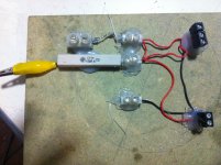
New Fets Arrived !
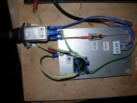
I keep blowing fuses .... I have checked one board and I'm with 1.5 VDC .
I unplugged it and plugged back in ... LOL fuse blew . Would an NTC across the
IRC stop it ?
I'm going to check the other board against the Voltages I have from Wayne . I'm checking one board at a time - the other board just blows the fuse as soon as I power it up !
Any guidance would be greatly appreciated
Rich
Attachments
Last edited:
then even worse , because we can't doubt jfets came from that direction
now is time for learning ; desolder , one by one , each semiconductor and test it
bjts with diode test , jfets in testing/matching jig
it really doesn't pay of , when you troubleshoot circuit randomly .
now is time for learning ; desolder , one by one , each semiconductor and test it
bjts with diode test , jfets in testing/matching jig
it really doesn't pay of , when you troubleshoot circuit randomly .
A simple way is to go for their IDSS without any RS (Source resistor) because jfets self bias pretty easily.
A 9V battery, and + to drain and - to gate/source shorted together. in series you put the mA meter, let them idle and just read values
For P types, just reverse the battery polarity
Best,
nAr
A 9V battery, and + to drain and - to gate/source shorted together. in series you put the mA meter, let them idle and just read values
For P types, just reverse the battery polarity
Best,
nAr
Check for shorts on the faulty board first with continuity meter. Probably a solder joint touches somewhere it shouldn't ...I keep blowing fuses .... I have checked one board and I'm with 1.5 VDC .
I unplugged it and plugged back in ... LOL fuse blew . Would an NTC across the
IRC stop it ?
I'm going to check the other board against the Voltages I have from Wayne . I'm checking one board at a time - the other board just blows the fuse as soon as I power it up !
Any guidance would be greatly appreciated
Rich
The read values seem fine at a quick glance except the -26.2 V at led reference point. Obviously value reading here should be : about 1,6V - 1,8V across LED1. Or, -22,4V to -22,2V between up leg (seen on schematic) of the LED and GROUND.
Best,
nAr
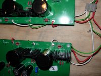
Ok , now I have got 6L6 lost too ... when I wire one board at a time to PSU all good ,but when both are wired the fuse blows ( no actives on either board- all voltages are good post Reg ) . I'm sure that .250 mA is advised for 240 AC - 3.15 at IRC
6L6 has checked pics of wiring and confirms its correct . I'll put some on here if needed .
Thanks , Rich
6L6 has checked pics of wiring and confirms its correct . I'll put some on here if needed .
Thanks , Rich
- Home
- Amplifiers
- Pass Labs
- Pearl Two