Ok, I have P1 and the led in the output stage and just 1 fet ( at the moment in the input )... i'll check the voltages then put the other 3 back in and post the voltage in the morning .
Rich - We are here to help. Please could you measure three voltages around Q3: collector (R9 side), base (R10 side) and emitter (Q6 side). Do this when only Q6 is installed, then when all Q6, Q7, Q8 and Q9 are installed. Next measure the voltage across each one of R21, R22, R23 and R24. And last but not least, the supply voltage at the other end of R9. All measurements relative to ground. I assume R9=499. Leave it that way.
Cheers - Pierre
We couldn't find more detailed way to proceed, thanks Pierre
")
Best,
nAr
Q3 with Q6 in place , Top = 13.66 , Gate = 9.88 , Bottom = 9.23 . Not too bad !
Now I need to measure my fets again .... I'm copying 6's method on post 1047 and getting .001 mA on them .. I'm not doing something right ?
Rich
Now I'm lost ... , measured again and I have 18.5 v drop across R9
Now I need to measure my fets again .... I'm copying 6's method on post 1047 and getting .001 mA on them .. I'm not doing something right ?
Rich
Now I'm lost ... , measured again and I have 18.5 v drop across R9
Last edited:
The drop of 18.5 v IS across R9 . With Q7 added .... Top = 2.7 v, Gate= 2.5 v, Bottom=2.3 v....
all readings fluctuate within .5 v
R
37 mA flowing ... average would be 13,5 mA/fet ... I assume you have 2 fets now ? Voltage fluctuating isn't good news. Check power dissipation on bipolars, are they hot, can you put fingers for long on them ?
2,3V @ emiter of Q3 is no good news. Correct me if I'm wrong. You should find here about 9 - 10 V ... the drains of jfet need about that to be in the good spot ...
Best,
nAr
To recap;
Post 1183 with one sk370, Q3 was good
Post 1185 you added one more sk370, Q3 voltages dropped
try a different sk370 in Q7
also the voltages Pierre would like are to ground, from either end of R9 to ground, not acress R9.
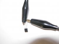
For sorting jfet, which pins are you holding together?
Post 1183 with one sk370, Q3 was good
Post 1185 you added one more sk370, Q3 voltages dropped
try a different sk370 in Q7
also the voltages Pierre would like are to ground, from either end of R9 to ground, not acress R9.
For sorting jfet, which pins are you holding together?
Last edited:
Momentary success ..... V was perfect for a few minutes 9.14 VDC then went down again 1.49 VDC .... . U1 is stable @ 24.09 VDC ... I have 20.00 @ top of R9 and 2.5 VDC at the bottom... So , Q1 is working fine ...
test Fets. with the curve facing away from me , I couple centre and right pin together ... as per post 1047
test Fets. with the curve facing away from me , I couple centre and right pin together ... as per post 1047
Momentary success ..... V was perfect for a few minutes 9.14 VDC then went down again 1.49 VDC .... . U1 is stable @ 24.09 VDC ... I have 20.00 @ top of R9 and 2.5 VDC at the bottom... So , Q1 is working fine ...
test Fets. with the curve facing away from me , I couple centre and right pin together ... as per post 1047
I'm sorry Rich, I'm out of ideas now - there's definitely something wrong with Q3 behaviour but I couldn't debug it
Either Q1 or Q3 show erratic behaviour. If Q1 still have the values steady as the general VDC, and Q3 wanders down, it might be Q3 the culprit.
Strange is you have one board that works perfect from that point of view. And no one could find the differences between boards !
If you use Dale resistors with special coding, be sure you haven't done a small mistake for spelling, installing a wrong value somewhere on the faulty board.
Best,
nAr
I removed Q7 and still Q3 is low .... the voltage @ Q1 is as it should be . Pulled R9 and it is 500R. Short of stripping the board and starting again ... ?
Hello Rich - it is possible that the jfet you did put in the Q7 spot was shorted.
Be mindful that the voltages that Wayne shared are for his particular jfet samples. My samples draw more current, and yours possible more than mine. So our Q3s all land in a different spot. What was 10 V for Wayne is 3 V for me, and you must figure out where Q3 will land for which devices in your case. Note that each jfet added below R9 draws current from R9 and brings Q3 further down. This is normal.
I note that your last measurements are different than those reported in Post 1137. I guess you were using different jfets. I calculate that the jfet of Post 1137 drew 5.2 mA. The last one your tried drew 12.6 mA. These figures are extremes for 2sk170BL which I assume is what you are using. Do you still have the jfet from Post 1137? It is a keeper. Let's try to find some that work and draw less than 12.6 mA.
Although I am no expert, I suspect that if the jfets draw a lot of current (high Idss), it is possible that using four devices in parallel brings the voltage at the bottom of R9 too close to ground. We can't change the value of R9 without changing the whole RIAA network (as Wayne kindly indicated). But no worries. The front end will operate with 3 jfets instead of 4. Or 2 for that matter.
At this point it would be useful if you tried two or three different jfets in the Q6 spot (one at a time) and measured all three voltages around Q3. You will want to label them
.Changing voltages can be due to many things. The voltmeter perhaps? Or cold solders? On Wayne's board, some pads connect to the ground plane, and require more heat to solder properly. Checking for cold solders is easy: I like to push and pull hard on every lead to verify that it does not move.
Pierre
Last edited:
Thank you most kindly for your help Pierre ,
I will need to test the fets again .... they were all mid 7's mA for the quad and
mid 8's for the diff pair .... I also have a handful of 370's that need to be measured ... . I'll try and figure out how test them and hopefully post the values tomorrow . I vaguely understand what you are saying ... the fets are drawing too much from Q3 , not leaving enough go around ? Basically , I need
to find lower current fets .
Rich
I had that happen when I strted Idss matching my fets. No reading. Indeed it turned out the fuse from my meter was blown.
Anyway, good luck with your Pearl II, I hope I'm not going to get into the same trouble as you.
By the way, my 2SK170 quads are 9.26-9.27mA and 9,30-9,36 mA. Should I change something in the schematic? (R10?)
Anyway, good luck with your Pearl II, I hope I'm not going to get into the same trouble as you.
By the way, my 2SK170 quads are 9.26-9.27mA and 9,30-9,36 mA. Should I change something in the schematic? (R10?)
- Home
- Amplifiers
- Pass Labs
- Pearl Two