after reading these groups for so many years, the following response wouldn't leave my head until i typed it.
apologies to nelson for badly butchering an earlier comment of his that i especially like ...
"we don't need no values; we are fearless preamp builders.
but we have spare jfets, just in case ..."

mlloyd1
btw, thanks wayne!
apologies to nelson for badly butchering an earlier comment of his that i especially like ...
"we don't need no values; we are fearless preamp builders.
but we have spare jfets, just in case ..."
mlloyd1
btw, thanks wayne!
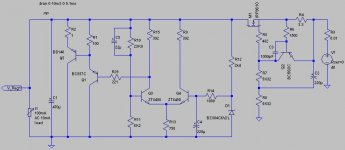
Here is the Pearl Two schematic. You will have to wait for values.
Here is the Pearl Two schematic. You will have to wait for values.
...or fully "open" the screen of your laptop and look at the schematic from a very open angle...and the values magically will appear...
sorry Wayne, it's 

And many, many thanks, I can't wait...
Only a comment: 7824/7924: there's room for improvement, I think
Guido
Only a comment: 7824/7924: there's room for improvement, I think
Just a suggestion - I was working on a VERY simple shunt regulator that is inspired by elements from previous "passdiy" designs, so it may actually fit here. The error amp is simply a differential pair, same as in the original Pearl series regulator, followed by two BJTs for the shunt element in place of the (series) FET in the original. The current source is basically a ZEN current source.
The circuit is very simple and you can off course get "better" performance (lower impedance) by means of higher amplification factor/feedback, through a more complex error amp (IC opamp or other) - there are numerous examples out there. And you can also go on for months toying with all kinds of variations but you may just be beating the subject to death (I spent a substantial amount of time on variations of the ctoole shuntreg and will not do this again).
At least my simulations look very promising and show flat load regulation over a very broad frequency range. I am quite confident that the circuit works well "as is" though I may be leaning myself out of the window a little bit by not having prototyped it. I am in the process of building such a prototype on a PCB, but that may take some time and you may not like my PCB version anyway, so if you are interested I strongly suggest not to wait and try it for yourself to see how it performs.
Attachments
...and the values magically will appear...
omfglol, this reminds me of U.S. military security defeated by copy and paste - CNET News
Just a suggestion - I was working on a VERY simple shunt regulator that is inspired by elements from previous "passdiy" designs, so it may actually fit here. The error amp is simply a differential pair, same as in the original Pearl series regulator, followed by two BJTs for the shunt element in place of the (series) FET in the original. The current source is basically a ZEN current source.
The circuit is very simple and you can off course get "better" performance (lower impedance) by means of higher amplification factor/feedback, through a more complex error amp (IC opamp or other) - there are numerous examples out there. And you can also go on for months toying with all kinds of variations but you may just be beating the subject to death (I spent a substantial amount of time on variations of the ctoole shuntreg and will not do this again).
At least my simulations look very promising and show flat load regulation over a very broad frequency range. I am quite confident that the circuit works well "as is" though I may be leaning myself out of the window a little bit by not having prototyped it. I am in the process of building such a prototype on a PCB, but that may take some time and you may not like my PCB version anyway, so if you are interested I strongly suggest not to wait and try it for yourself to see how it performs.
Babowana has attempted something akin once.
A power supply board will follow if anybody wants one. ???
Might not be a bad idea.
Thanks,
Jeff
Babowana has attempted something akin once.
Missed this one, in the meantime there are a zillion shunt regs out there. And yes, it is akin - this is after all a very common op amp topology. And to finally quote Babowana "I do not want to bore you with this". Same here.
Having said this, I recently built "Pearl" series regulators on the PCBs from the UGS groupbuy and used them on my B1 circuit (bipolar PS). The sound is exceptionally good with the Pearl regs, which is why I was beginning to question all the overly complex or sub-milliohm impedance designs out there.
Last edited:
A power supply board will follow if anybody wants one. ???
And with regulators? After all I was kind of trying to get you to reveal some of your tricks and ideas on regulators but I may have failed miserably here
The boards will be arriving after we return from CES in Las Vegas.
They are sized like the Pearl and will drop in. We will sell with matched fets.
A power supply board will follow if anybody wants one. ???
Would be a great deal! Power PCB is more of a luxury. If they would be available I would buy them though!
Missed this one, in the meantime there are a zillion shunt regs out there. And yes, it is akin - this is after all a very common op amp topology. And to finally quote Babowana "I do not want to bore you with this". Same here.
It was just a reference to see, because I guessed you have missed that.
Your's buffered, will work sharper. Still different taste than series no matter how good they get, I would encourage you to savor it with Pass and Wayne designs since you are in the process.Hello Massimo,
Zener was just for simulations since I had a model for it, I prefer to use a better reference. However, the Zener is filtered by an RC low pass so the Zener noise would not play much of a role here.
And no feedback is note quite correct, it has low and very linear feedback as far as I can tell, my sims went to beyond 10 MHz flat. Lastly we should probably not hijack the thread and turn it into a regulator discussion, some people may not be amused.
potentially noisy Zener ...
Zener was just for simulations since I had a model for it, I prefer to use a better reference. However, the Zener is filtered by an RC low pass so the Zener noise would not play much of a role here.
And no feedback is note quite correct, it has low and very linear feedback as far as I can tell, my sims went to beyond 10 MHz flat. Lastly we should probably not hijack the thread and turn it into a regulator discussion, some people may not be amused.
but I see a potentially noisy Zener ....
Sometimes you can change out a zener with a TVS (Transient Voltage Suppressor).
It doesn't regulate as well, but there is very little noise if you minimize the current through it.
My bench testing was with a bi-directional type. It had very little noise, like a resistor.
Sorry to drift off topic here... can't wait to see the circuit values for the Pearl v2!
- Home
- Amplifiers
- Pass Labs
- Pearl Two