The B1 buffer is essentially a voltage follower.
A voltage follower is also an essential part of a Linkwitz-Riley filter.
See this: Active Filters
Has anyone tried the B1 voltage follower as a component in a Linkwitz-Riley filter?
Here is my initial cut at a 2 pole LR filter using B1. This one crosses over at roughly 700 Hz (for my own personal project). Other frequencies are, of course, easily implemented. The filter seemed to lend itself to the symmetric supply topology, so that's what I have drawn here. I'm planning to use a beefed up Salas shunt regulator with this, as in the building-symmetrical-psu-b1-buffer thread.
Attachments
Hi Jacques Merde,
Thank you for posting your filter schematics.
That is the same approach I will take in the distant future for my 1KHz filter, safe that:
1) I can use balanced input signal from TVC so I will put a balanced to unbalanced input buffer instead of a B1.
2) Pots are usually noisier than good quality R so instead of using that 22K pot I will let fixed the HF output and only use a resistor based attenuator for adjusting the bass output. This brings more transparency to the sound, IMHO.")
Good luck,
M
Thank you for posting your filter schematics.
That is the same approach I will take in the distant future for my 1KHz filter, safe that:
1) I can use balanced input signal from TVC so I will put a balanced to unbalanced input buffer instead of a B1.
2) Pots are usually noisier than good quality R so instead of using that 22K pot I will let fixed the HF output and only use a resistor based attenuator for adjusting the bass output. This brings more transparency to the sound, IMHO.
Good luck,
M
brilliant!Here is my initial cut at a 2 pole LR filter using B1. This one crosses over at roughly 700 Hz (for my own personal project). Other frequencies are, of course, easily implemented. The filter seemed to lend itself to the symmetric supply topology, so that's what I have drawn here. I'm planning to use a beefed up Salas shunt regulator with this, as in the building-symmetrical-psu-b1-buffer thread.
It looks so simple. Unity gain and equal value R & C automatically gives Q=0.5 for the L-R function and makes it so simple to match components.
Be careful to check for DC at the outputs. Both at switch on and as the devices warm up. The low pass is particularly susceptible since it is completely DC coupled all the way through.
maxlorenz and AndrewT,
Thanks for the good suggestions. At the moment, I am more concerned with dealing with the issue of the Sallen-Key topology where, for the low pass filter, the finite output impedance of the buffer in combination with the feedback capacitor provides a for a forward signal shunt path which manifests itself as poor stop band response. In this case and with these component values, the difficulties are well within the audio band. This can be addressed in a number of ways, so I am back to the drawing board to do some thinking....
Cheers,
Attachments
Here is my initial cut at a 2 pole LR filter using B1. This one crosses over at roughly 700 Hz (for my own personal project). Other frequencies are, of course, easily implemented. The filter seemed to lend itself to the symmetric supply topology, so that's what I have drawn here. I'm planning to use a beefed up Salas shunt regulator with this, as in the building-symmetrical-psu-b1-buffer thread.
Hi everyone,
I think the circuit Jacques Merde posted here is fascinating, but can I ask a couple of possibly stupid questions?
1. Am I right in thinking the 22k pots shown in the circuit are trimpots, to set the relative levels for LP and HP? I presume the normal volume pots would come before this circuit altogether, right?
2. I presume "B+" and "B-" denote symmetric DC voltages from the power supply. Normal B1 values?
3. If you want to change the crossover point then you mess with the 22nF and 10.2k values throughout and leave everything else unchanged, correct?
4. At first sight this seems to be another place where one could use BF862 in place of 2SK170. The preamp juma designed (and which I may well build) uses the BF862 in a B1-type circuit with gain, to good reports. I've used the BF862 in a mini-aleph style amp (following juma's orientation), and like it a good deal. Is there any reason this circuit couldn't be done all SMD, with BF862 throughout? If you wanted to do this, what caps would you use?
Cheers
Nigel
each filter has a pair of equal R and a pair of equal C.
A crossover comprises a pair of filters.
That takes us up to 4off R and 4off C.
Stereo requires two channels. That brings our total to 8off R and 8off C.
For exceptional quality in rolloff and crossover characteristics and in channel matching all these R & C can be matched to <1% tolerance.
A crossover comprises a pair of filters.
That takes us up to 4off R and 4off C.
Stereo requires two channels. That brings our total to 8off R and 8off C.
For exceptional quality in rolloff and crossover characteristics and in channel matching all these R & C can be matched to <1% tolerance.
each filter has a pair of equal R and a pair of equal C.
A crossover comprises a pair of filters.
That takes us up to 4off R and 4off C.
Stereo requires two channels. That brings our total to 8off R and 8off C.
For exceptional quality in rolloff and crossover characteristics and in channel matching all these R & C can be matched to <1% tolerance.
Thanks. So, no matching of jfets (other than recommended for normal B1, I mean). Since close tolerance SMD components (resistors, anyway) are pretty cheap, wouldn't this be another reason for doing a surface-mount version? (Or did I miss something?)
Cheers
Nigel
Hi everyone,
I think the circuit Jacques Merde posted here is fascinating, but can I ask a couple of possibly stupid questions?
1. Am I right in thinking the 22k pots shown in the circuit are trimpots, to set the relative levels for LP and HP? I presume the normal volume pots would come before this circuit altogether, right?
2. I presume "B+" and "B-" denote symmetric DC voltages from the power supply. Normal B1 values?
3. If you want to change the crossover point then you mess with the 22nF and 10.2k values throughout and leave everything else unchanged, correct?
4. At first sight this seems to be another place where one could use BF862 in place of 2SK170. The preamp juma designed (and which I may well build) uses the BF862 in a B1-type circuit with gain, to good reports. I've used the BF862 in a mini-aleph style amp (following juma's orientation), and like it a good deal. Is there any reason this circuit couldn't be done all SMD, with BF862 throughout? If you wanted to do this, what caps would you use?
Cheers
Nigel
Hello Nigel,
1. Correct on both counts. My thinking is that the trimpots exist for the general case where one doesn't have advance knowledge of the system the crossover will be used in. Once the correct levels have been determined, the trimpots could be removed and replaced by jumpers and/or fixed resistor dividers for a more permanent installation.
2. Correct. I was thinking of +/- 9 or 10 volts, like the DCB1.
3. Correct.
4. I don't see any reason not to build this with a BF862. I haven't really put any thought into SMD cap selection at this point.
Thanks. So, no matching of jfets (other than recommended for normal B1, I mean). Since close tolerance SMD components (resistors, anyway) are pretty cheap, wouldn't this be another reason for doing a surface-mount version? (Or did I miss something?)
Correct, no special matching of JFETs, other than for Idss. As far as component matching goes, Panasonic 1% film caps are available from Digi-Key in those values, and 1% resistors are commonplace. AndrewT's thinking here is essentially identical to mine.
It's easier, for me anyway, to swap out leaded parts, but I don't see any reason not to build a SMD version.
These are all reasonable questions -- not stupid questions
I do have a solution for the low pass bandstop response issue, which I will post later.
Thanks,
Jacques,
Thanks for the answers.
I agree. Perhaps the moderators could split off the (still few) relevant posts in a new thread?
Cheers
Nigel
Thanks for the answers.
Jaq.
I think this is a cool design, worthy of it's own thread.
I agree. Perhaps the moderators could split off the (still few) relevant posts in a new thread?
Cheers
Nigel
Hello Nigel,
I do have a solution for the low pass bandstop response issue, which I will post later.
Thanks,
Waiting with baited breath
I've almost finished sorting my 100 jfets into 0.5ma ranges, the timing of you posting this Jacques is very good indeed, I'm very happy I have dilly dallied around and not built a conventional B1 with PLXXO because *this* is what I really wanted Thank you for posting!! Tony.
This has generated enough interest that I think it makes sense to start a separate thread, so here it is. If the moderators could move the relevant posts from the B1 Buffer Preamp thread to here it would be much appreciated.
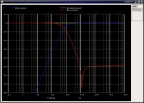
A solution to the bandstop response issue in the low pass section is to provide a separate buffer for the feedback cap, blocking the forward signal path to the output. This increases the stopband attenuation to greater than 100 dB.
I've eliminated the trimpot from the LP section, as I don't need it in my particular application.
I've been busy with work, but I'll post more here as soon as I get an opportunity.
Cheers,
Attachments
Your schematic have a serious error!
/RK
Could you be more specific?
Sorry, was not reading your text
Seems you intentionally do not have a connection from the p section to the output buffer.
You say: "A solution to the bandstop response issue in the low pass section is to provide a separate buffer for the feedback cap, blocking the forward signal path to the output. This increases the stopband attenuation to greater than 100 dB"
Hi, I've only read the first few pages of the B1 thread, but am I right in assuming this is the B1 with a LR crossover? Good for people who want to bi-amp if so.
May I ask if it's 24db/oct or 12db/oct? Also, what is the crossover frequency?
The relevant posts over in the B1 Buffer Preamp thread are: 2012, 2017, 2019, 2021, 2026, 2027, 2028, 2029, 2030, 2031, 2032, 2033, 2034 & 2035.
This a 2 pole (12dB/oct) LR filter at 700 Hz. It should be fairly straightforward to implement 24dB/oct.
If the moderators could move the relevant posts from the B1 Buffer Preamp thread to here it would be much appreciated...The relevant posts over in the B1 Buffer Preamp thread are: 2012, 2017, 2019, 2021, 2026, 2027, 2028, 2029, 2030, 2031, 2032, 2033, 2034 & 2035.
Done. Supplying the post numbers is greatly appreciated.
dave

- Status
- This old topic is closed. If you want to reopen this topic, contact a moderator using the "Report Post" button.
- Home
- Amplifiers
- Pass Labs
- B1 Active Crossover