Hi rgheck!
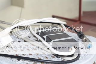
you'll be disappointed cause i'm not a real DIYer (sic). I didn't want to get in trouble building a power supply and i got this kit from Cebek at local store, Spanish manufacturer similar to Velleman. It's variable from 12 to 24 Vdc 500mA, i adjusted to 18V and voila!
Cost = 24€ = 30$ = headaches because designing a PS = 0
fuente var. 12 a 24v 500ma - Diotronic
I'm sure you can get similar PS at Radio Shack, Digikey, Mouser or your nearest electronic stuff store.
Hope it helps!
Last edited:


")
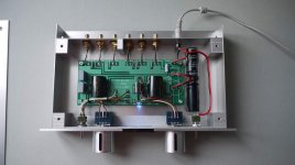
I have finished a B1 that is powered by an old HP deskjet printer supply. I must say that it was fun to build. This nice little piece sounds astonishing well. For a low enclosure profile I have dislocated the caps off the board.
Attachments
Wow! Martin, your build looks fantastic!
Here is my humble B1 to be added to this thread, many more photos and information in this link -- http://www.diyaudio.com/forums/pass-labs/181552-b1-preamp-build-thread.html
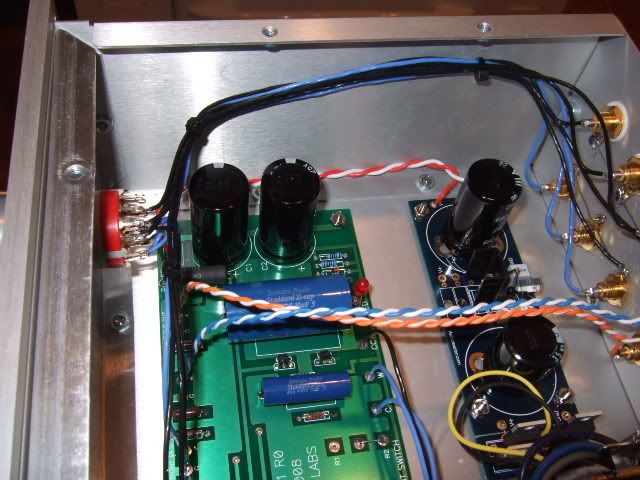
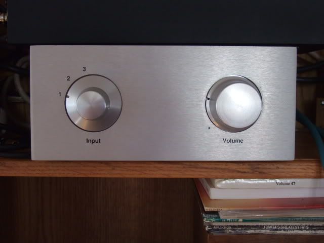
Pass boards, Peter Daniel PSU board w/LM317 regulator
Here is my humble B1 to be added to this thread, many more photos and information in this link -- http://www.diyaudio.com/forums/pass-labs/181552-b1-preamp-build-thread.html
Pass boards, Peter Daniel PSU board w/LM317 regulator
Hi,
Im just finishing up a point to point B1.
I wanted to ask about the 1M resistor from input to ground. Since im not using a board is there a preferred place to put it? I can put them on the rca inputs or i thought i could put them on the volume pot between its input and ground.
Should be the same but any thoughts?
thanks
I have finished a B1 that is powered by an old HP deskjet printer supply. I must say that it was fun to build. This nice little piece sounds astonishing well. For a low enclosure profile I have dislocated the caps off the board.
Martin,
How did you make the B-1 lighting effect? Very nice!
Eric
B1 current draw
I built a B1 using the Pass board.
It is silent and works exactly as it should with one problem.
To test it I used 2 9volt batteries in series to supply the 18v.
It works fine but seems to draw an awful lot of current.
Within 5 minutes the batteries are getting warm and are about used up after 20 minutes or so.
Any ideas?
Thanks.
thanks 6L6 i do that..Try the RCA first, and see how it sounds (I.E., hum) It there is a problem, then try on the pot.
i tested the build the other day but i did not include the 1M resistor (i forgot it). It seemed to sound fine.. this was only using a mp3 player as a source.
So is the 1M necessary for all sources? Just curious i will be putting them in..
Banned
Joined 2002
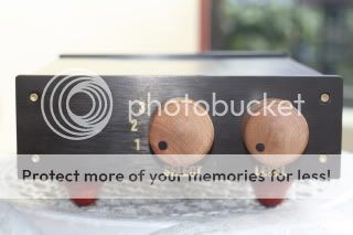
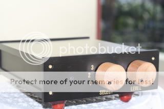
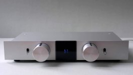
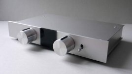
thought i would share a couple of pis of my build.
I decided to go point to point and integrate am mp3 player into the unit... not quite finished, i have to finish mounting the mp3 player and add the faceplate to it and the feet and knob are temporary for the pics also considering adding some leds to give it a glow but not sure yet..
I decided to go point to point and integrate am mp3 player into the unit... not quite finished, i have to finish mounting the mp3 player and add the faceplate to it and the feet and knob are temporary for the pics also considering adding some leds to give it a glow but not sure yet..
An externally hosted image should be here but it was not working when we last tested it.
An externally hosted image should be here but it was not working when we last tested it.
Hi,
the B1 & F5 have a gain of +15.5dB.
The signal level at the B1 input needs to be higher than usual. 3.5Vpk for maximum output. A CDP is normally capable of ~3Vpk at maximum.
The 27W into 8r0 becomes ~36W into 6r0.
This will give a maximum of ~100dB SPL at 2.5m from a pair of 89dB speakers.
In a 42 sqm room, I would not consider that sufficient.
Last edited:
- Status
- This old topic is closed. If you want to reopen this topic, contact a moderator using the "Report Post" button.
- Home
- Amplifiers
- Pass Labs
- B1 builders thread