Hello. I'm interested in building Zen head-amp and now designing PCB for this.
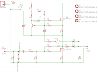
My PCB design is based on Marcello Pellerano's PCB, which can be found here:
HeadWize - Project: The Zen Headphone Amplifier by Marcello Pellerano
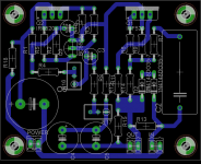
So here is my version. It's a bit smaller then "original" and I also tried to minimize the total length of tracks, were signal is flowing...
Waiting for comments and advices.
After all I'll share Eagle file here.
My PCB design is based on Marcello Pellerano's PCB, which can be found here:
HeadWize - Project: The Zen Headphone Amplifier by Marcello Pellerano
An externally hosted image should be here but it was not working when we last tested it.
So here is my version. It's a bit smaller then "original" and I also tried to minimize the total length of tracks, were signal is flowing...
An externally hosted image should be here but it was not working when we last tested it.
Waiting for comments and advices.
After all I'll share Eagle file here.
Member
Joined 2009
Paid Member
Twitchie,
Rodeodave,
PCB size is ~85*72mm (with mounting holes)
Inputs cap (C2): Wima MKP4 or other (LS 10.2, 15, 22.5 mm);
Output caps (C9,C10): Panasonic FM 470uf or another (LS 5mm); Elnas are too big
Power Cap (C6): Panasonic FC or other ( LS 7.5mm)
Bigun,
It will be dual mono, so both channel will be just this PCB*2. Maybt I'll made stereo version later (but to be honestly, I'm not realy interested on this )
thanh1973,
I have read about DAO, and I even believe, that it's better then ZEN (lol), but:
1. DAO need bigger enclosure, bigger filter caps, bigger trafo... Maybe next time
2. I'm afraid I need some voltage gain...
3. There aren't any complete Guide for DAO amp, and my skills are not good yet, I'm DIY noob
Done. Thank You.Maybe flip R3 and R10 and eliminate the jumper, then you could also straighten up the track between R10, R11 and Q2
Rodeodave,
Added Lead spacing 10.2 and 15mm. Need any more?Concerning C2: Maybe add more holes to support various footprints/sizes.
An externally hosted image should be here but it was not working when we last tested it.
PCB size is ~85*72mm (with mounting holes)
Inputs cap (C2): Wima MKP4 or other (LS 10.2, 15, 22.5 mm);
Output caps (C9,C10): Panasonic FM 470uf or another (LS 5mm); Elnas are too big
Power Cap (C6): Panasonic FC or other ( LS 7.5mm)
Bigun,
It will be dual mono, so both channel will be just this PCB*2. Maybt I'll made stereo version later (but to be honestly, I'm not realy interested on this
)thanh1973,
I have read about DAO, and I even believe, that it's better then ZEN (lol), but:
1. DAO need bigger enclosure, bigger filter caps, bigger trafo... Maybe next time
2. I'm afraid I need some voltage gain...
3. There aren't any complete Guide for DAO amp, and my skills are not good yet, I'm DIY noob
Last edited:
The only thing I would probably do differently, with this design, is I would remove the active bias circuit.
A headphone amp really doesn't need an active bias circuit, I would bias it between 600mA to 1A. This will sound better than lowering the bias down with the active bias circuit.
The main benefit I see for the active bias circuit is you can use smaller heatsinks.
A headphone amp really doesn't need an active bias circuit, I would bias it between 600mA to 1A. This will sound better than lowering the bias down with the active bias circuit.
The main benefit I see for the active bias circuit is you can use smaller heatsinks.
1. DAO need bigger enclosure, bigger filter caps, bigger trafo...
That depends on the bias you want to run. I have a version running at +/-16V, 100mA. and you don't need much heatsink for that.
2. I'm afraid I need some voltage gain...
Not if you have low impedance phones (e.g. AK701).
3. There aren't any complete Guide for DAO amp
That is true, I am too lazy / busy with other projects .....
But I am sure Steen or James would help you.
There isn't really much in the circuit, especially the original version.
But then who am I to tell you to build the DAO instead of Nelson's designs !!
Patrick
Last edited:
Twitchie, nice looking layout.
I'm only worried about very long and thin track from V+ to first IRF.
Are You planning building this? And why IRF520?
P.s. Nelson Pass used some MKT(MKS) caps to bypass power and output in ZEN4 , maybe we should add them to this design too?
I'm only worried about very long and thin track from V+ to first IRF.
Are You planning building this? And why IRF520?
P.s. Nelson Pass used some MKT(MKS) caps to bypass power and output in ZEN4 , maybe we should add them to this design too?
Last edited:
Hi Twitchie,
nice layout, but please consider that "high" bias currents need some copper: it is not necessary to oversize this aspect, you needc to calculate it correctly. In a quasi non-feedback circuit (few dBs....) even the current modulations can be heard through (sensitive) headphones. IMHO I don't see IRF520 very well in this circuit. It has been design around IRF610 types, with the 520s the frequency response will not be enought for a quality result.
As suggested, you can successfully defreat the bias modulation with slightly acoustic upgrade, but yuo will need to crank up the bias current to compensate. And yes, with my Grado's and my AKGs (701, 141M) I need gain too, if I want to connect the amplifier straightly to the Micromega CD setup outputs.
Good Work! : )
Marcello
Thanks for the comments Tortello and I should thank you as well for your original contributionSorry, I guess I should clarify - I've been on a diyAudio break with a new baby and my computer got reimaged so I just downloaded Eagle and it didn't have IRF610 so I just used 520 for the layout and pinout.
I was hoping for the feedback regarding trace widths. To be honest, I enjoy all aspects of diy equally so I may or may not ever etch this and even if I do, I may or may not get to populate it and even then ... you get the picture, but I do have fun all the way along.
I moved the layout around a tiny bit to make room for wider traces. I'll repost when I get enough time between diaper changes

Hi Twitchie,
please etch, populate, and enjoy your amplifier, and if you want let me know what are you thinking about.
But only when your babies sleep, otherwise... enjoy your babies!!
If you can't have a selected set of 610s, please drop me your address: as time permits I will be very glad to send them to you.
Marcello
- Status
- This old topic is closed. If you want to reopen this topic, contact a moderator using the "Report Post" button.
- Home
- Amplifiers
- Pass Labs
- Zen headamp. PCB, my ver.