To their credit, they have now changed the design.
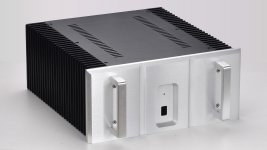
A choice between 2 front panels, no engraving.
On Both Sides Of The Radiator Weiliang JC3 Circuit All Aluminum Chassis All Aluminum Amplifier Chassis 3415|Amplifier| - AliExpress
Patrick
.
A choice between 2 front panels, no engraving.
On Both Sides Of The Radiator Weiliang JC3 Circuit All Aluminum Chassis All Aluminum Amplifier Chassis 3415|Amplifier| - AliExpress
Patrick
.
Attachments
I've built my clone on EUVL's boards and had everything per his schematic. I was only getting about 4.5 mA through R33. Bias was about 1.35 A on the output devices with the output offset nulled. Seemed reasonable at just a bit over the 1.2 A I've seen suggested.
Trying to get the current through the frontend up to 8.5mA, I changed R33 to 187 Ohms but now I can't null the offset. The Rdg pot is turned all the way down to 0.5 Ohms and I still have about 3.5 volts on the output.
Not understanding how to get the offset further down I'm actually thinking that I was good at the start before changing R33. Isn't the drop across R33 the current through just Q2? So at about 4.5 mA across R33 and the output nulled the current should be the same through both Q2 and Q3 at about 9mA total. Is this correct?
Cheers
Rick
> Trying to get the current through the frontend up to 8.5mA, I changed R33 to 187 Ohms
8.5mA refers to the current in Q1, and NOT R33.
R33 will normally see half of that, i.e. 4.3mA.
There is NO need to change the value of R33 unless you want to change the front end bias to 17mA at Q1.
I see no reason for that, but if that is what you want, then you have to double up to use 2x Q1 (either 2SK170 or J113) in parallel.
A single JFET will not take the dissipation.
For trimming DC offset, you should only adjust Rdg, and not R33.
Rdg will allow you to fine adjust the current through Q1.
Patrick
WOW !!!!
How far will some people go :
SEMISOUTH SJEP120R100 SiC POWER JFET with Populated AMP PCBs and FW CHASSIS | eBay
Patrick
How far will some people go :
SEMISOUTH SJEP120R100 SiC POWER JFET with Populated AMP PCBs and FW CHASSIS | eBay
Patrick

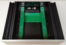
Single input transistor, positive rail supply (but separate secondaries, one for each channel ...it seems... the PS PCB says Dual Mono Power Supply...) an optocoupler and AC sound coupling capacitor bank at the output. I am not that familiar with the FW amps range... maybe someone else can narrow it down?
On a separate note, I think the guy should stop selling publicly the blatant rip off of the original design. That's what I call a hardened criminal.
On a separate note, I think the guy should stop selling publicly the blatant rip off of the original design. That's what I call a hardened criminal.
Attachments
Is that measured at 100kHz?aroundish 45db
I’ve put aside some pairs of curve trace matched R100 and some j109/j74 in case, by miracle, production ever ends and the circuit is made public and blessed by Papa.
I’ve also hoarded some other matched and unmatched pairs.
I’ve got a bit if a JFETish.
So in the mean time, I build using sockets to avoid damage to my unobtanium so I can reuse them in different designs.
Most recent build is a pair of Babelfish J2. I’ve built them all IRFP first for testing…still troubleshooting some noise in one. Once they are both good I’ll plug in the SS and make appropriate resistor adjustments and reset bias and offset.
I’m curious to compare ZMs all IRFP to SS down and possibly an all SS version.
I also have Jeff Youngs J2 boards that I wanted to try.
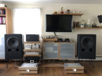
Currently using F2J in my sunroom system with OB and the J2 were last in the main system bi-amping Tannoys.
I’ve tried SS down in ACA as well…they added the usual improvements. I left them in for now even though I don’t use them much. I would like to build two more channels and bridge them along with SS to see the results.
I work slow…🐌
I’ve also hoarded some other matched and unmatched pairs.
I’ve got a bit if a JFETish.
So in the mean time, I build using sockets to avoid damage to my unobtanium so I can reuse them in different designs.
Most recent build is a pair of Babelfish J2. I’ve built them all IRFP first for testing…still troubleshooting some noise in one. Once they are both good I’ll plug in the SS and make appropriate resistor adjustments and reset bias and offset.
I’m curious to compare ZMs all IRFP to SS down and possibly an all SS version.
I also have Jeff Youngs J2 boards that I wanted to try.
Currently using F2J in my sunroom system with OB and the J2 were last in the main system bi-amping Tannoys.
I’ve tried SS down in ACA as well…they added the usual improvements. I left them in for now even though I don’t use them much. I would like to build two more channels and bridge them along with SS to see the results.
I work slow…🐌
Attachments
"This is supposed to be a diy"
DIY is not equal to carbon copy.
https://www.diyaudio.com/community/threads/first-watt-website-update.358313/post-6299428
https://www.diyaudio.com/community/threads/first-watt-f8.358672/page-7#post-6654823
Patrick
DIY is not equal to carbon copy.
https://www.diyaudio.com/community/threads/first-watt-website-update.358313/post-6299428
https://www.diyaudio.com/community/threads/first-watt-f8.358672/page-7#post-6654823
Patrick
- Home
- Amplifiers
- Pass Labs
- FirstWatt J2