Nigel, corrected schematic is given in posts #28 and #31. Since you are building 4 preamp modules, you'll have to double the current, so what you need is:
40mA from neg. reg. - 80ma total (shunt burns the same ammount of current as the preamps)
80mA from pos. reg - 160mA total.
You set that with R22 and R23 for pos. reg. and R11 for neg. reg. (half the value of those resistors). Some heatsinking is neccessary - I use the heatsinks from dead PC PSUs - they are large enough and have threaded holes for MOSFETs (Q11, Q9, Q3 and Q7).
Thanks juma, that's all very clear (and now I know what to do, I'll sit down and try to understand better *why*...
") ) The schematics on posts #23 and #28 are the same, I believe, so the only thing that needs changing is C14, correct? As far as heatsinking goes, I have a box filled with loads of heatsink bits and pieces - something like what you suggest will be OK, although I may have to bend things around a bit to fit.
) The schematics on posts #23 and #28 are the same, I believe, so the only thing that needs changing is C14, correct? As far as heatsinking goes, I have a box filled with loads of heatsink bits and pieces - something like what you suggest will be OK, although I may have to bend things around a bit to fit.I finished building the PSU circuit as shown in the posts above last night, before I realised I may have current problems. The adjustments you describe above can be done with no problem; however the voltages I'm getting are slightly different; +24.3 and -5.1. I'm not at all concerned with the positive voltage, which I'm sure is fine, but you stress above how critical the negative regulator circuit is. I would expect that it's the stability of the voltage that's the issue, not it's value, correct? Nonetheless, do you think it's worth the effort tweaking this voltage down a little? (The cheap DMMs I'm using to measure this may not be perfectly accurate, of course, and it''s only a 10% difference...)
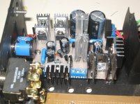
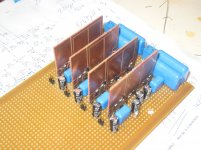
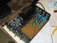
Here are a couple of photos of progress. The big bare board will have all the buffers on it - the idea is to put buffer circuits on PCBs and mount them vertically to help with heat. Since I need a whole bunch of identical buffers this means I can sort of mass-produce them...Power for the filter buffers is a problem still to be completely solved, but the preregulation is handled by the part already done.
Cheers, and thanks for the help!
Nigel
Attachments
That I guess we'll never know.... and now I know what to do, I'll sit down and try to understand better *why*...

Generaly they are, but #28 has all the diode's and capacitor's polarities right (except for C14)...
The schematics on posts #23 and #28 are the same, I believe, so the only thing that needs changing is C14, correct?
You get -5.1V because your zener diode is not quite 3V9, I guess it's more like 4V3 or so (no matter what's written on it). Measure the voltage drop accross that zener and put the right one (real 3V9). If you measure 3.9V there then you possibly messed something else.... the voltages I'm getting are slightly different; +24.3 and -5.1. ...
If you can't make it to -4.6V use the -5.1V but then you'll have to change the Source resistor of the first JFET from 470 R to 510R and then you'll have about 10% less gain in that stage (1.8V/V instead 2V/V).
Filter buffers are simple CCS loaded Source Followers and that's a circuit with really great PSRR. You'll have to have a very high resolution system and very sharp ears to notice the difference (nuances) between 7809/7909 regs and best shunt regs when used to supply this buffer with power. I wouldn't worry too much about that. Just take some care of local decoupling....Power for the filter buffers is a problem still to be completely solved..
Hi juma,
Uh... the only difference I can see is that #23 has the 7915 and filter after it. Did I miss something (Hope not, because I built #23, since I *have* a 7915...) All polarities are the same in the two schematics... right? (Even C14, which is wrong in both.)
Aha! seems quite likely... I'll measure and post the answer.
Now that's interesting... On the other thread AndrewT suggested separate regulators for each channel and for LP and HP. (Total of four). This is impractical with the Salas discrete regs I was planning, but would be quite simple with 7809/7909 (which is what I think AndrewT had in mind, although he wasn't specific). By "decoupling" here you mean the usual caps, right?
This is definitely worth some thought. (good thing I have some time before I build that stage... )
Do the heatsinks in the photo I posted look to you like they'll be adequate? The black one in lower right I think is a bit dodgy (it's on the shunt mosfet in the +ve reg, which has to dissipate most power, right?) so I think I'll try to change for something larger. I'm hoping the others are OK.
Cheers, and thanks again
Nigel
That I guess we'll never know
Generaly they are, but #28 has all the diode's and capacitor's polarities right (except for C14)
Uh... the only difference I can see is that #23 has the 7915 and filter after it. Did I miss something (Hope not, because I built #23, since I *have* a 7915...) All polarities are the same in the two schematics... right? (Even C14, which is wrong in both.)
You get -5.1V because your zener diode is not quite 3V9, I guess it's more like 4V3 or so (no matter what's written on it). Measure the voltage drop accross that zener and put the right one (real 3V9). If you measure 3.9V there then you possibly messed something else.
Aha! seems quite likely... I'll measure and post the answer.
Filter buffers are simple CCS loaded Source Followers and that's a circuit with really great PSRR. You'll have to have a very high resolution system and very sharp ears to notice the difference (nuances) between 7809/7909 regs and best shunt regs when used to supply this buffer with power. I wouldn't worry too much about that. Just take some care of local decoupling.
Now that's interesting... On the other thread AndrewT suggested separate regulators for each channel and for LP and HP. (Total of four). This is impractical with the Salas discrete regs I was planning, but would be quite simple with 7809/7909 (which is what I think AndrewT had in mind, although he wasn't specific). By "decoupling" here you mean the usual caps, right?
This is definitely worth some thought. (good thing I have some time before I build that stage...
)Do the heatsinks in the photo I posted look to you like they'll be adequate? The black one in lower right I think is a bit dodgy (it's on the shunt mosfet in the +ve reg, which has to dissipate most power, right?) so I think I'll try to change for something larger. I'm hoping the others are OK.
Cheers, and thanks again
Nigel
Better use less current mirror shunts than revert to 3 legged general reg chips. There is sufficiently low output impedance in the discrete regs so the interaction between client audio circuits to be adequately low. Try to sub the Zeners with resistors and use larger caps across them. The subjective definition will leap up. Also explore remote sensing. Just an example in the attached picture. R10 can be a mutliturn 10k. That will let you have precise Vout(s) also. Shunt regs were very effective in the DCB1S after using LM317/337 for some reason. Same on even higher PSRR OPA627 line stages after IC regs and after batteries. Maybe its the CCS part in the shunts not moving current dynamically in the lines before the regs, don't know.
Attachments
Hi Salas,
Thanks for your answer. I'll likely have some questions once I have had a chance to study your circuit a bit, but I wanted to clarify something in case it wasn't clear... The whole project includes 18 buffers; the four output buffers are like the ones on this thread, the other 14 are symmetric buffers in a system of active filters. For the output buffers the PSU will definitely be discrete, since it is already built ; the question of using 7809/7909 is for the active filters, which obviously need different regulators, since voltages are different (+/- 9V).. For these the original plan was to adapt your circuit from the symmetrical B1 thread, but current demand is quite high (14 buffers drawing about 13mA each), so my query on another thread started this idea (AndrewT's suggestion) of using 2 or 4 pairs of regs.
(Of course, if allthis was already clear, my apologies...)
Cheers
Nigel
Thanks for your answer. I'll likely have some questions once I have had a chance to study your circuit a bit, but I wanted to clarify something in case it wasn't clear... The whole project includes 18 buffers; the four output buffers are like the ones on this thread, the other 14 are symmetric buffers in a system of active filters. For the output buffers the PSU will definitely be discrete, since it is already built
; the question of using 7809/7909 is for the active filters, which obviously need different regulators, since voltages are different (+/- 9V).. For these the original plan was to adapt your circuit from the symmetrical B1 thread, but current demand is quite high (14 buffers drawing about 13mA each), so my query on another thread started this idea (AndrewT's suggestion) of using 2 or 4 pairs of regs. (Of course, if allthis was already clear, my apologies...)
Cheers
Nigel
use one "global" CCS for several locally situated shunt reg parts
I was wondering about something a little like this, although I'm not sure I know how to do it. I'm going to try and post a schematic later...
or use one global shunt reg for several stages , where each stage have own cap multiplier
I'm sorry ZM, I've used cap mutlipler PSUs before, but I don't understand what you're suggesting here...
Ditto. ''Works like glue'' as Papa would have said. I would prefer the former for output impedance reasons. Gyrators are also good filters but have relatively high and irregular Zout.
A "gyrator" is another name for a cap multiplier?
Sorry if these are more stoopid questions...
Cheers
Nigel
A "gyrator" is another name for a cap multiplier?
Sorry if these are more stoopid questions...
Cheers
Nigel
Next of kin.
Capacitance Multiplier
Gyrator
Thanks Salas. I'll take a look later.
Meanwhile, I'm troubleshooting the -ve regulator... The voltage of -5.1 I queried above was due in part to a wiring error. (Source of Q7 not adequately grounded.) However, now that is fixed I'm getting -4.1V... The voltage across the zener D1 is 3.2, not the 3.9 expected, which may be the problem, but for some reason I doubt this. Vbe on Q6 and Q4 is larger than I expected (0.69V and 0.75 V) and that, summed with the 3.2 across the zener nicely gives (almost)the output voltage. It is as though there isn't enoughvoltage across the zener for it to regulate it...
A couple of (stupid) questions, if I may.
1. How much variation in Vbe should I see in this circuit? I thought it ought to be just about a fixed constant?
2. Remembering I'm using the schematic from post #23, since I am using a 7915 prereg, is it possible that there just isn't enough input voltage for the circuit to work properly? I measure over 5 volts across R16, so there is only about 10 V (smoothed) entering the rest of the circuit, as compared to the schematic in post #28, where 9V AC is rectified and therefore gives about 12.6 (unsmoothed).
3. Any reason I can't put a resistor (say 1k) in parallel with R16 to lower resistance a little and (?) raise the voltage provided to the rest of the circuit? It shouldn't break anything? This could be aq way to test 2.
Of course it'll probably turn out to be some stupid mistake on my part... but I'd be grateful for any answers, nonetheless.
Cheers
Nigel
Hi,
if the current passing the 3v9 Zener is low then the Zener will measure a low voltage.
Can you estimate the Zener current?
Multiply that current times the 3.9V to find the power that the Zener is dissipating.
This should be >5% of max dissipation and preferably >=10% of max power.
A 400mW 3v9 Zener can pass a maximum of 102mA and for good Zener operation needs >5mA and preferably >=10mA to get well past the knee in the V vs Iz curve.
A pair of green LEDs + a low value resistor will probably work better than a low voltage Zener in this position. Alternatively, a pair of red LEDs and a higher value resistor.
Can you check how well the CCS is working? Does it hold a fairly constant current at the low voltage (4.6V) you are trying to achieve?
Last edited:
Hi,
if the current passing the 3v9 Zener is low then the Zener will measure a low voltage.
Can you estimate the Zener current?
Multiply that current times the 3.9V to find the power that the Zener is dissipating.
This should be >5% of max dissipation and preferably >=10% of max power.
A 400mW 3v9 Zener can pass a maximum of 102mA and for good Zener operation needs >5mA and preferably >=10mA to get well past the knee in the V vs Iz curve.
A pair of green LEDs + a low value resistor will probably work better than a low voltage Zener in this position. Alternatively, a pair of red LEDs and a higher value resistor.
Can you check how well the CCS is working? Does it hold a fairly constant current at the low voltage (4.6V) you are trying to achieve?
I just bought some more zeners to see if this is the problem. I'm going to try a test circuit with one of them first, to see if they are marked correctly, and will then try some of the thing you suggest. Interesting, what you say about needing >5%... Makes sense once pointed out, and may be part of the problem, since I can only get 1/2 or 1W zeners here.... In any event, I'll fire up the soldering iron this evening, and we will see...
Cheers
Nigel
GB for Jumas PCB
Hi All, Sorry about my absence from the forum for the past month +. Holidays and work made diya impossible for a while. If there is still enough interest in a GB for this board I would like to continue where I left off.
I started a GB thread http://www.diyaudio.com/forums/group-buys/158425-gb-bf862-preamp-jumas-work.html#post2043518 and I added everyone that was originally interested to the spreadsheet on this link http://bit.ly/bf862signup .
I ask that if you would like to confirm your pcb(s) please do so in the GB thread.
Thanks,
Nick
Hi,
if the current passing the 3v9 Zener is low then the Zener will measure a low voltage.
Can you estimate the Zener current?
Multiply that current times the 3.9V to find the power that the Zener is dissipating.
This should be >5% of max dissipation and preferably >=10% of max power.
A 400mW 3v9 Zener can pass a maximum of 102mA and for good Zener operation needs >5mA and preferably >=10mA to get well past the knee in the V vs Iz curve.
A pair of green LEDs + a low value resistor will probably work better than a low voltage Zener in this position. Alternatively, a pair of red LEDs and a higher value resistor.
Can you check how well the CCS is working? Does it hold a fairly constant current at the low voltage (4.6V) you are trying to achieve?
Good call, AndrewT!! I measured voltages again and estimated around 11mA going through R6 and R12, which looks to me like it should be all the current going through the zener. Now the datasheet for the zener says it's a 1W device, so I was most likely on the knee of the curve, just as you predicted... I switched the zener out for a 500mW device and got a much better voltage, with 4.03 across the zener, and changing again for one that showed 3.93V I have 4.66V on the output... which is close enough, I'd say...
A very sharp call on your part... Do you give tips for the Grand National?
Cheers, and thanks...
Nigel
A progress report and a disaster!!!
I'm having a strong drink to calm my nerves after discovering the most ridiculous mistake in my construction of this preamp... If you have the patience to read to the bottom you can have a good laugh at my expense...
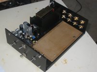
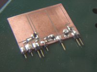
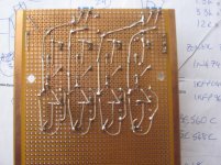
I've taken a couple of afternoons of work this week, as a sort of holiday, and I've spent them soldering.... Things have progressed well: I've attached a few photos that show the four output buffers I need for my project. The four PCBs each contain the three jfets and all surrounding resistors, all SMD, to make one channel ofthis preamp, but with all capacitors on the main board. In the second photo you can see how the four are designed to stand upright (for better heat dissipation - possibly unecessary but can't hurt) and better use of space (definitely an issue with this project). The third photo shows the p2p wiring on the bottom of the main board, although without power and earth connections. The fourth photo shows everything mounted and ready to test two of the output buffers, although all wiring between boards is just temporary.
So I checked for Dc offset and so forth, and there being no problem I connected everything up and hit "play" on John Coltrane's "Blue Train", hoping to hear " veils lifted" and so forth, only to hear instead a thin, distorted, horrible (althouh recognizable) sound... Worse, it's exactly the same on both channels, so (probably) not a bad earth connection or something easy...
I dug around on this and other threads to see if I had made a simple mistake wiring the volume pots or something like that, and checking one of juma's opsts I found the mistake... You can see it for yourself on the first photo, where the source resistor on the middle jfet says "1001"....:
Of course, in retrospect I should have checked the schematic in post #23 more thoroughly after juma alerted me to possible problems, so the fault is all mine... and fortunately I have plenty of 10R SMD resistors on hand, but unfortunately (as you can see in the second and fourth photo) to change them is a major "unbuilding" job... Oh well... I know how tomorrow afternoon is going to be spent...
Cheers
Nigel
I'm having a strong drink to calm my nerves after discovering the most ridiculous mistake in my construction of this preamp... If you have the patience to read to the bottom you can have a good laugh at my expense...
I've taken a couple of afternoons of work this week, as a sort of holiday, and I've spent them soldering.... Things have progressed well: I've attached a few photos that show the four output buffers I need for my project. The four PCBs each contain the three jfets and all surrounding resistors, all SMD, to make one channel ofthis preamp, but with all capacitors on the main board. In the second photo you can see how the four are designed to stand upright (for better heat dissipation - possibly unecessary but can't hurt) and better use of space (definitely an issue with this project). The third photo shows the p2p wiring on the bottom of the main board, although without power and earth connections. The fourth photo shows everything mounted and ready to test two of the output buffers, although all wiring between boards is just temporary.
So I checked for Dc offset and so forth, and there being no problem I connected everything up and hit "play" on John Coltrane's "Blue Train", hoping to hear " veils lifted" and so forth, only to hear instead a thin, distorted, horrible (althouh recognizable) sound... Worse, it's exactly the same on both channels, so (probably) not a bad earth connection or something easy...
I dug around on this and other threads to see if I had made a simple mistake wiring the volume pots or something like that, and checking one of juma's opsts I found the mistake... You can see it for yourself on the first photo, where the source resistor on the middle jfet says "1001"....
: Of course, in retrospect I should have checked the schematic in post #23 more thoroughly after juma alerted me to possible problems, so the fault is all mine... and fortunately I have plenty of 10R SMD resistors on hand, but unfortunately (as you can see in the second and fourth photo) to change them is a major "unbuilding" job... Oh well... I know how tomorrow afternoon is going to be spent...
Cheers
Nigel
Attachments
No biggie there, it could happen to anyone
What worries me more is your layout, those big copper surfaces and long traces - I pray it works all right in the end
It's turning out to be tough to get the pcbs off the main board to change the resistor... I'm considering trying to touch-solder a nornal resistor in parallel, which would look ugly but might be less intrusive than breaking everything apart to get the boards off...
The big copper surfaces are there to help with the heat generated by the gates. (Shouldn't be too bad, but I thought something ought to be done.) The only long trace I'm worried about is the input, all others are nice and short, and in this case the input will have to go through several other buffers before it even gets to these, so I figured it was a small concession to keep eveything else short.
I'll post later and let you know how things turn out.
Cheers
Nigel
- Home
- Amplifiers
- Pass Labs
- BF862 Preamp