Any stable DC source, its only a utility. Get a 2SK170 low IDSS, 2N5459 ,or any other 5-6mA IDSS NJFET, connect its drain at B(+), connect its G&S together, crock lead LED's anode there too. Return cathode to (-). Measure Vf across lit LED. Stick it on paper, note its Vf. Repeat for some. Do the sorting later picking from the noted bunch. Alternative and more precise to a resistor.
Thanks Salas,
I was just wondering about the method, stable DC source.
I've done the matching 3 times, very close measures.
I'll try to match 2SK170 too")
Schematic here : Transistor matching
I was just wondering about the method, stable DC source.
I've done the matching 3 times, very close measures.
I'll try to match 2SK170 too
Schematic here : Transistor matching
2SK170BL Matching session today about 100 units.
Results using the previous posted link schema :
6.51/6.52 - 6.61/6.62 - 6.67/6.67 - 6.95/6.96
7.11/7.12/7.13 - 7.17/7.18 - 7.26/7.27 - 7.39/7.39 - 7.48/7.49 - 7.65/7.65 - 7.94/7.94
8.16/8.16/8.16 - 8.49/8.49 - 8.81/8.81 - 8.83/8.83 - 8.96/8.97
9.93/9.94
10.91/10.92
About 18 pairs/trio found.
Question
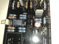
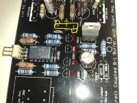
Which of them should I prefer using in Q1/2 and Q3/4 position as shown in this pic ?
Thanks
Results using the previous posted link schema :
6.51/6.52 - 6.61/6.62 - 6.67/6.67 - 6.95/6.96
7.11/7.12/7.13 - 7.17/7.18 - 7.26/7.27 - 7.39/7.39 - 7.48/7.49 - 7.65/7.65 - 7.94/7.94
8.16/8.16/8.16 - 8.49/8.49 - 8.81/8.81 - 8.83/8.83 - 8.96/8.97
9.93/9.94
10.91/10.92
About 18 pairs/trio found.
Question
Which of them should I prefer using in Q1/2 and Q3/4 position as shown in this pic ?
Thanks
Attachments

Well that was easy...
... I wrote some time ago about the DCB1 sounding odd because it was rolling off as the frequencies got into the midrange and got progressively worse through the treble. I did three things to it and it straightened out. I changed out the gate stoppers for some carbon composition types (was using Koa Spear metal films) replaced the volume control and increased the current in the regulator to 100 ma. I suspect that the regulator current was just too low. I now have a little DC offset in the output of 1.2 mV and .6 mV where it was not measurable before.
Didn't listen to it very long as I will need to use the heat sinks on the MOSFET's now but the depth of stage is impressive. Now I can start trying a few things to see what the final values are going to be. I'm going to go to 150 ma on the regulators and see how that works out.
Now it's getting to be fun again.
Last edited:
... I wrote some time ago about the DCB1 sounding odd because it was rolling off as the frequencies got into the midrange and got progressively worse through the treble. I did three things to it and it straightened out. I changed out the gate stoppers for some carbon composition types (was using Koa Spear metal films) replaced the volume control and increased the current in the regulator to 100 ma. I suspect that the regulator current was just too low. I now have a little DC offset in the output of 1.2 mV and .6 mV where it was not measurable before.
Didn't listen to it very long as I will need to use the heat sinks on the MOSFET's now but the depth of stage is impressive. Now I can start trying a few things to see what the final values are going to be. I'm going to go to 150 ma on the regulators and see how that works out.
Now it's getting to be fun again.
First at all, why did you knew that it was rolling off? Did you used measurement equipment to check it? Or did you use any software tester like rightmark and a soundcard?
Because I have, and mine outputs straight as a line. Please, do that before making assumptions based on subjective impressions. Post your picture from rightmark too so we can aim to diagnose your problem.
Going from metal films to carbon composition is not going to make any objective difference.
I understand your concern with the subjective side of this. However... it was so obvious that there was a problem and I don't really have anything at my disposal to use for measurement. The sound was not unlike that of turning the treble all the way down to the -10 db mark on an integrated amplifier. Sorry I cannot provide anything more than that for now.
I Googled Rightmark which looks interesting. I'll look into that as time permits. Life requires me to tend to too many other things for now.
I Googled Rightmark which looks interesting. I'll look into that as time permits. Life requires me to tend to too many other things for now.
Last edited:
Probably it was oscillation. We are talking about the audio part gate stoppers?
Yes. I had ordered the wrong type of resistor for the input. I had intended to just use that to make the circuit work before I ordered any of the 'audio quality' resistors recommended in the BOM.
- Home
- Amplifiers
- Pass Labs
- Building a symmetrical PSU B1 buffer