Are you sure those films aren't 0.22uF and not 2u2? There is no film cap value that can do harm. It just that some members found Wima 0.22u blending well in the sonic mix.
I thought MKS2XL was over 10uf. They are MKS2 then. 2u2 is fine as well.
Yes, they're 2u2 MKS2XL.
Your pcb looks nice and orderly BTW.
Thank you, Salas
")
Any suggestion regarding the 10 Ohm resitor ?
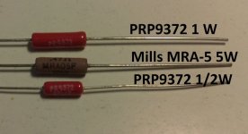
MOX / Mills / Kiwame /etc.
the PCB has space for 2resistor on top. Two more can be fitted underneath attached to the legs of the top two.
30r will dissipate ~130mW (22% of 600mW).
Three 30r gives the same current as one 10r. and looks far neater.
There is room for a fourth resistor to trim the current to what you want. Any value >=30r can be used for final trimming.
I certainly would not put a bulky multiwatt resistor for setting CCS current.
Found some strange things yesterday and today:
Oscillation:
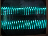
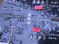
I got oscillation at about 2.5MHz in both sides of the PS . It was visible everywhere, but with highest amplitude on the 47 Ohm resistor, side of the 2SK170 (see pic 1 lower trace). On the output I had a ripple of 7mvpp. Not audible at all, but on the scope it was visible (see pic 1 upper trace 5mv/div). A higher value of the outputcaps (see later) lowered the amplitude, but didn't make it disappear for 100%. A small cap over base and collector of Q3 stopped the oscillation completely (I guess this lowers the bandwidth of the regulation). I still have no idea where it came from. Maybe from the non-isolated cooling plates of the fets, creating a capacity. I guess to be safe I should put a resistor in series with the cap, but with 10nF it's working stable like a rock now. There is really zero ripple on the PS and on the output. See pic 2 for the location of the cap. On that pic you also see the modif I did to the relais to avoid an extra contact. I checked voltages during start and stop, I don't think the jfet is suffering. I also drilled the holes to have symmetrical connections for the inputs, still have to cut the traces.
Caps:
I did the cap-mod (replacing a 100uF by a small one) too quickly, I replaced the wrong caps . This gave just 100nF at the final buffer position (this low value made the oscillation very visible). Today I moved the 100nF to where they belong, // to the 5 LEDs. I had some unused Mundorf Mcaps 2.2uF hanging around. As 100nF was enough on the output buffer, I tought this 2.2uF should do as well. And indeed, sounds great. Compared to yesterday (with 10nF against oscillation, 100uF on LEDs and 100nF on output), it sounds a lot more open today (10nF, 100nF on LEDs, 2.2uF on output). The difference is big. Yesterday I moved from song to song after 30 seconds of listening, today I listened every song till the end. Maybe I was tired yesterday evening
  . But it's clear that today the music is more "everywhere" in the room. Yesterday it was closer to the speakers.
Before putting the 10nF for oscillation, and still with 100uF everywhere, the soundstage was a lot smaller. In the meanwhile I cleaned the speaker connections, that could have changed the sound as well.
To be sure about the size of the cap, I put a 270R load on the outputs, and drove the inputs really hard. There was no influence on the PSs at all. I'm confident this value of 2.2uF is enough.
PCB:
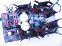
Last pic is the pcb, before I solder it in the amp. I used other diodes as I still had those in stock. I also drilled some holes to improve airflow (will not help a lot, but is used in tubes as well. I'm sure I will hear the extra air in the soundstage clearly).
There is a 1M resistor where the 220k should be. That's because I have a 50k pot at the moment. I will change it as soon as I have a new pot installed.
BTW, I read a lot of remarks on the quality of the PCB. I had no issues at all, even after resoldering different components several times. Only the protective film gives a strange small and becomes ugly on some points. And a lot worse: it's really difficult to take pictures.
Oscillation:
I got oscillation at about 2.5MHz in both sides of the PS
. It was visible everywhere, but with highest amplitude on the 47 Ohm resistor, side of the 2SK170 (see pic 1 lower trace). On the output I had a ripple of 7mvpp. Not audible at all, but on the scope it was visible (see pic 1 upper trace 5mv/div). A higher value of the outputcaps (see later) lowered the amplitude, but didn't make it disappear for 100%. A small cap over base and collector of Q3 stopped the oscillation completely (I guess this lowers the bandwidth of the regulation). I still have no idea where it came from. Maybe from the non-isolated cooling plates of the fets, creating a capacity. I guess to be safe I should put a resistor in series with the cap, but with 10nF it's working stable like a rock now. There is really zero ripple on the PS and on the output. See pic 2 for the location of the cap. On that pic you also see the modif I did to the relais to avoid an extra contact. I checked voltages during start and stop, I don't think the jfet is suffering. I also drilled the holes to have symmetrical connections for the inputs, still have to cut the traces.Caps:
I did the cap-mod (replacing a 100uF by a small one) too quickly, I replaced the wrong caps
. This gave just 100nF at the final buffer position (this low value made the oscillation very visible). Today I moved the 100nF to where they belong, // to the 5 LEDs. I had some unused Mundorf Mcaps 2.2uF hanging around. As 100nF was enough on the output buffer, I tought this 2.2uF should do as well. And indeed, sounds great. Compared to yesterday (with 10nF against oscillation, 100uF on LEDs and 100nF on output), it sounds a lot more open today (10nF, 100nF on LEDs, 2.2uF on output). The difference is big. Yesterday I moved from song to song after 30 seconds of listening, today I listened every song till the end. Maybe I was tired yesterday evening . But it's clear that today the music is more "everywhere" in the room. Yesterday it was closer to the speakers.Before putting the 10nF for oscillation, and still with 100uF everywhere, the soundstage was a lot smaller. In the meanwhile I cleaned the speaker connections, that could have changed the sound as well.
To be sure about the size of the cap, I put a 270R load on the outputs, and drove the inputs really hard. There was no influence on the PSs at all. I'm confident this value of 2.2uF is enough.
PCB:
Last pic is the pcb, before I solder it in the amp. I used other diodes as I still had those in stock. I also drilled some holes to improve airflow (will not help a lot, but is used in tubes as well. I'm sure I will hear the extra air in the soundstage clearly).
There is a 1M resistor where the 220k should be. That's because I have a 50k pot at the moment. I will change it as soon as I have a new pot installed.
BTW, I read a lot of remarks on the quality of the PCB. I had no issues at all, even after resoldering different components several times. Only the protective film gives a strange small and becomes ugly on some points. And a lot worse: it's really difficult to take pictures.
Attachments
the PCB has space for 2resistor on top. Two more can be fitted underneath attached to the legs of the top two.
...
I certainly would not put a bulky multiwatt resistor for setting CCS current.
Hi Andrew,
effectively the pcb has space for 3 resistors in these positions.
So, If I've understood, the needed power is 600mW and 3x 1/2W resistors in parallel would do the trick, right? (I'm not good with math...)
Anyway the Mills MRA5 is not bigger than a 1W PRP...
Attachments
Caps:
I did the cap-mod (replacing a 100uF by a small one) too quickly, I replaced the wrong caps
So when you got the 2.5MHz oscillation you just had 100nF across reg's output? And then still a little with 100uF? What ESR?
Plastic output caps are better if someone compensates in the error amp, but it takes experience and an oscilloscope as you know/did.
P.S. I run what you did on LT Spice, it spends enough phase margin without a little ESR in the output cap if with film, so the Cdom is a necessity, and its a juggling act, so its trial n' error as you did. The Cdom eats closed loop gain of course on the other hand. Maybe a 0.33R in series with the 2.2u could save you the Cdom. Then again you have found a good tweak set subjectively and its stable on bench...
P.S.2 The thing with the gate current through audio fets when muting to ground could be if having strong signal on them. Unlikely when someone mutes or shuts down but mentionable.
Is it possible to build one of these with balanced and S/E inputs and outputs? I have a few things in my system that are balanced like my DAC. My current amp is S/E though and I have some sources that are S/E as well.
You would need double builds to assign each phase to one I would suppose, but I haven't done it. My system is SE.
Might have to try that out.... I was thinking I could do the one with the source selection but, I've been eying the AC1 from twistedpear. So maybe I'll build the basic version.
I have quite a bit of PCB material so might just try etching finally lol.
What have you guys found the cost of parts to stuff the boards is?
I have quite a bit of PCB material so might just try etching finally lol.
What have you guys found the cost of parts to stuff the boards is?
Someone's looking to use XLR in the regular B1 thread too, made a schematic, I suppose it will interest you. http://www.diyaudio.com/forums/pass-labs/124889-b1-buffer-preamp-253.html#post2228753
As for cost, differs a lot with ''special'' parts or not, overspec trafos etc. Other members may give you some range, me I built the protos from existing components in my hobby stash, some recycled even, and I can't estimate.
As for cost, differs a lot with ''special'' parts or not, overspec trafos etc. Other members may give you some range, me I built the protos from existing components in my hobby stash, some recycled even, and I can't estimate.
Hi Salas
I had a Vishay MKP1837 100nF on the output when I had the oscillation, seems it has very low ESR. I tried to put the elco in parallel, now I understand why it didn't help as the Vishay still kept ESR low.
I don't like a resistance in series with the output cap, as that would lower the buffer/impedance of the power supply, leaving more influence coming from the error-amp. I prefer to live with the lower closed loop gain. BTW, can you estimate the difference in bandwidth in Spice? Anyhow the end result is OK now, and that counts for me. Maybe I could put a resistor in series with this new cap, but I'm afraid that will result in unstable behaviour.
Yesterday I built the PCB in my preamp, bypassing everything but input-relais and pot. The result is astonishing. I didn't know my speakers went that low. And more important, it keeps an incredible control of the lows, this was not always the case with the tubes. Also voices and cymbals are great. My tube-amp never achieved this amount of details. And the same preamp completely passive (into 100KOhm input impedance of power amp) also didn't give the same power. Now music is in the room instead of coming from the speakers.
Great design, great thread !
[special=P.S. I run what you did on LT Spice, it spends enough phase margin without a little ESR in the output cap if with film, so the Cdom is a necessity, and its a juggling act, so its trial n' error as you did. The Cdom eats closed loop gain of course on the other hand. Maybe a 0.33R in series with the 2.2u could save you the Cdom. Then again you have found a good tweak set subjectively and its stable on bench...]%[/special]
Nice to have feedback from a Spice simulation, it takes away my worries that there was something wrong in my B1.I had a Vishay MKP1837 100nF on the output when I had the oscillation, seems it has very low ESR. I tried to put the elco in parallel, now I understand why it didn't help as the Vishay still kept ESR low.
I don't like a resistance in series with the output cap, as that would lower the buffer/impedance of the power supply, leaving more influence coming from the error-amp. I prefer to live with the lower closed loop gain. BTW, can you estimate the difference in bandwidth in Spice? Anyhow the end result is OK now, and that counts for me. Maybe I could put a resistor in series with this new cap, but I'm afraid that will result in unstable behaviour.
Yesterday I built the PCB in my preamp, bypassing everything but input-relais and pot. The result is astonishing. I didn't know my speakers went that low. And more important, it keeps an incredible control of the lows, this was not always the case with the tubes. Also voices and cymbals are great. My tube-amp never achieved this amount of details. And the same preamp completely passive (into 100KOhm input impedance of power amp) also didn't give the same power. Now music is in the room instead of coming from the speakers.
Great design, great thread !
Hello, nice results. Have a great time with it.
*ESR or technically added R in the output caps does not up reg's Zo because its a shunt capacitor. I could give you some cook ups of smaller Cdom and some added R for your 2u2 favorites, and I have seen the closed loop gain in Spice with the 10n huge Cdom from the start, but I will not tease you since you got the sound that you like. Its a PCB not a proto and too many experiments will destroy it.
Don't worry, be happy.
- Home
- Amplifiers
- Pass Labs
- Building a symmetrical PSU B1 buffer