BA-1 Single Ended
I have collected the transformers and associated parts to build this and other amps. Now that I am retired, I have some choices to make.
My intention is to build a single ended 3 pairs per channel IRFP040 (12 total both channels) stereo amp.
I have 4 ohm speakers and need some advise which voltage 1000 VA transformer I should use to maximize output power at 4 ohms.
I am using current inventory, not buying anything new, if I can help it.
Antek 1000VA:
So a 0-18, 0-18, 0-18, 0-18 VAC (23 VDC 1 amp per device)
Or a 0-25, 0-25, 0-25, 0-25 VAC (32 VDC .75 amp per device)
Which transformer would be best to use?
My heatsinks will handle over 150 watts per side.
Rush
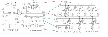
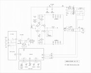
I am not in any way gifted in electronics. I have been trying to assemble the BA-1 and do not understand how to interface the front end and output stage.
It seems to revolve around D and S but it is unclear to me
Any advice would be appreciated
see pic
I have collected the transformers.....
more than 3 pairs per channel could be wise
")
Attachments
Zen Mod;5909586 more than 3 pairs per channel could be wise :)[/QUOTE said:ZM,
Well, I only have 12 matched devices. I don't think you can buy them anymore.
Rush
Wow...IRFP040? I seem to recall those were pretty rare even back in the original Zen days.
Dennis,
I think so.
Someone said they sounded better than currently available Mosfets, but that is probably because you can't get them, even back then. If they are unobtainium, then of course they sound better!
Rush
On alternative mosfets for Zen amp :
On IRFP040 vs. IRFP044 :... the best choice for the N channel device in my experience is the IRFP040, which is no longer made.
The 040 is doped a little differently than the 140 or 240 and the lower withstand voltage comes with higher transconductance, which accounts for the better performance...
Thus The Wizard hath spoken.The real difference is that you can get the 044's. I just scored a thousand of them.
Thank you for the help. It is clear now
see pic
more than 3 pairs per channel could be wise
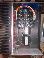
Building the amp in an old Threshold 4000 chassis
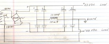
In the process of laying out the power supply and caps and I wanted to use a smoothing choke instead of resistors in a CLC configuration.
Well, I am running out of room. Can't stack the 2 chokes (too tall) can place them side to side (too wide). Could place the front to back, but crowding the rear plate and I might need to place the BA3 input board there and the choke will be awfully close.
So I started to think. I remembered in the Tube days, you could place the choke in the ground instead of the high voltage side of the power supply.
So tell me if this configuration has merit, see attached.
Rush
Attachments
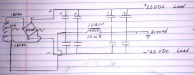
in tube days , choke in GND was in "return" route (there was not negative rail) ...... here is not - on amp's side practically everything is happening between two rails ...... gnd being practically bored 
I had same brilliant idea several years ago , then someone did told me the same thing ; when I learned to sim a little , I checked and it is that way
in case that you're using "split" choke , one winding in positive and second in negative (appropriately phased) , that will be other thing ......
I had same brilliant idea several years ago , then someone did told me the same thing ; when I learned to sim a little , I checked and it is that way
in case that you're using "split" choke , one winding in positive and second in negative (appropriately phased) , that will be other thing ......
in tube days , choke in GND was in "return" route (there was not negative rail) ...... here is not - on amp's side practically everything is happening between two rails ...... gnd being practically bored
I had same brilliant idea several years ago , then someone did told me the same thing ; when I learned to sim a little , I checked and it is that way
in case that you're using "split" choke , one winding in positive and second in negative (appropriately phased) , that will be other thing ......
OK, then I will do it this way.
Rush
See you at BAF this year
Attachments
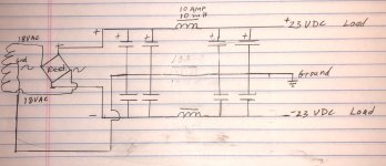
these two chokes are separate ones ?
funny me ...... I never remember proper phasing of "differential" or how it is called anyway - choke , but luckily there is NEM AI-50 thread on forum , with properly drawn choke
find it enclosed , to save you of search ......
Attachments
these two chokes are separate ones ?
......
Yes, separate ones.
Rush
BA1 Power Supply
Here is a picture so far. Test fitting front and back panels and right heatsink.
Made a new back panel, haven't completed all the holes yet. I'll paint it after the work is done.
I'll rotate the transformer to shorten the secondary leads.
I was hoping to make the amp lighter than the original 200 watt Threshold Class A.
The old transformer was 27 pounds, the new one is 17 pounds. The 10 pound difference was eaten up by the 13 pounds of chokes. Probably going to weigh the same 83 pounds. (Which is too much for my bad back.)
Rush
Attachments
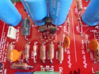
2SJ109BL is factory packed pair of single JFet , marked 2SJ74BL
so , we can use nicely matched pair of these instead , and they will fit in same pinout for 2SJ109BL , just looking in opposite direction
sticky thread in forum is giving you some info where to obtain them - easiest to visit Forum Store and look for current Linear Systems production - see LSJ74B type
- Home
- Amplifiers
- Pass Labs
- Burning Amplifier BA-1